
Indexed In
- Genamics JournalSeek
- JournalTOCs
- CiteFactor
- RefSeek
- Hamdard University
- EBSCO A-Z
- OCLC- WorldCat
- Publons
- Google Scholar
Useful Links
Share This Page
Journal Flyer
Open Access Journals
- Agri and Aquaculture
- Biochemistry
- Bioinformatics & Systems Biology
- Business & Management
- Chemistry
- Clinical Sciences
- Engineering
- Food & Nutrition
- General Science
- Genetics & Molecular Biology
- Immunology & Microbiology
- Medical Sciences
- Neuroscience & Psychology
- Nursing & Health Care
- Pharmaceutical Sciences
Research Article - (2020) Volume 9, Issue 1
Improving Impact Toughness for Welding Joints of Steel by Adding TiO2 Nanoparticales
Ali Fakhri Al-Obaid1*, Ali Sadiq Yasir2 and Sabah Mresn Thahab32Mechanical Engineering Department, Faculty of Engineering, University of Kufa, Najaf, Iraq
3Nanotechnology and Advanced Materials Research Unit (NAMRU), Faculty of Engineering, University of Kufa, Najaf, Iraq
Received: 26-Nov-2019 Published: 03-Feb-2020, DOI: 10.35248/2168-9873.20.9.323
Abstract
The using of nanotechnology in the welding process has great importance in developing the mechanical properties of welding joints for metals. This paper investigated the effect of addition TiO2 NPs to welding joints to improving the Impact toughness property of the welding joints. The cold spray coating method of the nanoparticles are used to adding the TiO2 NPs to the welding joints during the welding process. Three weight fraction are used for TiO2 NPs (0.75%, 1.5%, and 2%). The testing samples were prepared for Impact test, and microstructure by SEM. The results show the increasing in Impact toughness of welded joints with an increase of TiO2 NPs concentrations. The average Impact toughness for the welded sample without TiO2 NPs. was (162.4 J), while the average Impact toughness for the welded sample with (1.5)% TiO2 NPs. was (231.2 J) with improving rate of (42.36%). The Microstructure images by SEM show the adding of TiO2 NPs decreases the grain size and homogenous region in welded joints cross-section compared with a sample without adding TiO2 NPs. The EDS analysis show that increase Ti contain and decrease (Mn and Si) contain with increase TiO2 NPs.
Keywords
Steel welding; TiO2 nanoparticles; Nano welding; Impact toughness
Introduction
Titanium dioxide (TiO2) NPs were used to create a new types of metal matrix composite materials (MMCM) in many engineering applications. TiO2 NPs have many suitable properties because of chemically stability, exhibits an efficient photocatalytic effect and nontoxic effects [1,2]. The disadvantages of traditional epoxy additives such as glass and rubber beads can be control of the application of TiO2 rising the strength, stiffness, and toughness without reducing its thermo-mechanical properties [3]. Also, the other types of TiO2, as well as TiO and Ti2O3, show the mechanisms of rising nucleation rate and ferrite grain delayed growth lead to effectual in rising the number of nucleation locations for intragranular acicular ferrite in welding zones [4-9]. During welding process, the decrease of TiO2 lead to the existence of titanium in the weld zone that may produce TiC, TiN and Ti2O3 results. In the weld zones, there are four kinds of ferrite can be appearing: intragranular acicular, grain boundary allotriomorphic, Widmanstätten, and intragranular idiomorphic. The intragranular acicular ferrite phase increase with increasing the TiO2 NPs. Its fine microstructure, nucleates intragranular in the shape of separate strips on non-metallic implying inside austenite grains [10]. The best combination of mechanical properties due to increase in density of high angle grain boundaries.
The different of crystallographic orientation in Grain boundaries lead to change crack growing direction by stand-in as strong barriers [10-13]. Fattahi et al. studied improving the mechanical properties of welding zone by the addition of TiO2 NPs to the electrode coating and investigated the effect of nucleation of intragranular ferrite. It was presented that the quantity of Titanium in the weld zone rising an acicular ferrite, while the Mn and Si quantities were reduced.
Also, the rise in the amount of Mn-Ti complex oxide inclusions in the welding zones lead to variation in the microstructure of columnar zones from Widmanstätten ferrite and allotriomorphic ferrite to fine intragranular ferrite. The other influence was improved the tensile strength and impact toughness properties of the welding zones due to the ultrafine grain size of the ferrite for the reheated zones [14]. Pal et al. used wire electrode consists of (1.5%) TiO2 micro particles, but (33.333)% of the TiO2 micro particles was replaced by TiO2 NPs. Four sample were tested, two samples without TiO2 NPs and two samples with TiO2 NPs through welding They obtained an improvement rate in tensile strength and Charpy impact [15].
The electrode coating by TiO2 NPs achieved improving in mechanical properties of the weld zones [14,15]. In this paper, the effect of TiO2 NPs on the Impact toufghness, the nucleation of intragranular ferrite, and microstructure of weld metals will be carried out in investigated using the cold spray coating method to add nanoparticles on welding joints. The Impact toughness and Microstructure of welded joints will be tested using addition TiO2 NPs through the thickness of welded joints of St-37 low carbon steel by using standard specification.
Experemental Work
Three weight percentage (Wt%) of TiO2 NPs colloidal (0.75, 1.5, and 2)% was added to weld metal by the cold spray coating method were provided from US Research. Inc., anatase type with an average particle size (10-25) nm. The wire electrode AWS E6013 (4 mm diameter) was used to weld specimens. St-37 base metal was used for this research with dimensions of (250 mm × 200 mm × 20 mm). The chemical analysis of wire electrode and base metal are presented in Table 1.
| Sample | C | Si | Mn | P | S | Cu | Cr | Ni | Mo | V |
|---|---|---|---|---|---|---|---|---|---|---|
| Base material | ≤ 0.13 | 0.1-0.4 | 0.2-0.5 | 0.05 | 0.035 | 0.03-0.05 | 0.05-0.08 | 0 | 0 | 0 |
| Wire electrode | 0.2 | 1 | 1.2 | N.S | N.S | 0 | 0.2 | 0.3 | 0.3 | 0.08 |
Table 1: Chemical analysis (Wt %) of core wire electrode (E6013) and base metal (St-37).
The colloidal of TiO2 NPs was prepared by dissolving of (2.76, 5.53 and 7.37 g) in (20 ml) of distilled water to provide (0.75, 1.5 and 2)% wt. respectively according to equation (1) by using Magnetic Stirrer instrument (Jenway Company, UK), and mixed by Ultrasonic mixing liquid instrument (MTI Corporation company, USA) in the nanotechnology unit at the Faculty of Engineering at the University of Kufa.
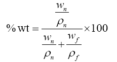 (1)
(1)
Where:
wn =weight for nanoparticles (g)
ρn=density for nanoparticles (3.9 g/cm3 for TiO2 (anatase))
wf =weight of welding filler (g)
ρf =density for welding filler (7.64 g/cm3)
The cold spray coating method was used to add the TiO2 NPs colloidal to each pass of welding process. The welding zone was coated by TiO2 nanoparticle after cleaning of the welding slag after measuring of temperature of the welding zone before coating process. It was found that the best adhesives of TiO2 NPs obtained at 300°C temperature. Followed by another welding layer. It was observed that the temperature of the welding zone before the coating was an important factor. Also at high temperatures greater than 500°C gets rapid drying in TiO2 nanoparticle colloidal was occurred leading to a situation of flaking and non-adhesion of TiO2 NPs on the welding zone. While at low temperatures less than 200°C, the colloidal was dried slowly so that the colloidal was pushed out of the welding zone, because of the pressure of the air compressor. The temperature measurement was done by the manual infrared thermometer instrument. The St-37 specimens were lathing in mechanical workshop of the Kufa cement plant.
Impact test
A 20-mm thickness (St-37) low carbon steel was used and cut to (190 mm × 125 mm), and the preparation of Impact toughness specimen was (25). Five specimens from base metal (B), five of which were welding without the addition of nanoparticles (W), and the remaining fifteen by added of TiO2 NPs (0.75, 1.5, and 2)%, (S1, S2 and S3) respectively, five specimens for each ratio. The weld dimensions of the weld pool for the preparation and formation of the Impact toughness specimen were as shown in Figure 1 [16,17]. The specimens were welded by E6013 (4 mm) wire electrode dimeter at 200 A current by AC welding Machin, and then tested the welding by portable ultrasonic flaw detector instrument to detect the defects of welding before testing. Since the plate used for the design and preparation of specimen was 20 mm, the number of passes to fill the entire weld pool was fourteen pass distributed over seven layers (two pass for each layer) [17]. As according to our research procedure, the added nanoparticles were distributed only to the four middle layers because they are the only ones that include the diameter of the tensile specimen type and according to the method of addition nanoparticle mentioned above. Therefore, there was no need to add nanoparticles to the welding layers at the top and bottom of the welding area. After the full weld pool was filled.

Figure 1: Specimen of impact testing.
The specimen's surfaces were scraped a 5 mm by milling machine for each surface of the specimen. Final thickness of the specimens was 10 mm. The specimens were then being cut to 55 mm long and 10 mm width by an automatic horizontal band saw as shown in the Figure 1 with coolant solution [16,17]. The milling machine was used to preparation the weld specimen as shown in Figure 2. The impact testing was performed on a V-notched specimen with (500 J) value of kinetic energy. The specimens are fixed horizontally and hit with a heavy pendulum. The pendulum speed is about 4.8 m/s. Note that all operations were carried out at the mechanical workshop at Kufa Cement Plant. The type of instrument was used (HECKRT, Company, Germany origin) in the Applied Mechanics Laboratory at the Faculty of Engineering at the University of Kufa.

Figure 2: Impact specimens after the test.
In this test, five specimens were cut by hand saw which taken from round tensile specimens after testing. One of the specimen of the base metal (B) and one of the specimen welding without the addition of nanoparticles (W) and three specimens welding with the addition of (0.75, 1.5 and 2)% TiO2 NPs (S1, S2, and S3), one test sample for each added of the specimen surface as shown in Figure 2.
Microstructure image test
In this test, five specimens were cut by hand saw which taken from round tensile specimens after testing. One of the specimen of the base metal (B) and one of the specimen welding without the addition of nanoparticles (W) and three specimens welding with the addition of (0.75, 1.5 and 2)% TiO2 NPs (S1, S2, and S3), one sample for each ratio.
The specimen dimensions were (Ø 13 × 10 mm). After the cutting process, the specimen surfaces were prepared, grinding and polished by the grinding and polished instrument, and used in the grades of grinding paper (240, 320, 400, 600, 800, 1000 and 1200) respectively. The time of the grinding surface of the specimen was five minutes for each paper grinding. Then polishing the surfaces with alumina emulsion materials for a five minutes for each specimen. The surface of the specimen was etched with 2% Nitric acid (Nital) in water, by immersing the surface of the specimen for one minute in the solution. Following washing the surface with distilled water and drying it with hot dry air. The type of instrument was used the optical microscope instrument (1600X) (MTI Corporation Company, 1600X, USA origin) in the laboratories of the Nanotechnology Unit at the Faculty of Engineering at the University of Kufa with magnification power (10X) was used. Five microscopic tests were taken at the centre of the surface for each specimen and four others at a (0, 90, 180, 270) degree of the specimen surface as shown in Figure 3.

Figure 3: Location of tested points.
FE-SEM and EDS tests
The selected specimens for (FE-SEM) test and (EDS) test were the same specimen used in microstructure test as shown in Figure 4. The tests were point and mapping. The type of instrument of FESEM and EDS tests was used (TESCAN, Mira 3, French origin).

Figure 4: The prepared specimens for SEM and EDS tests.
Results and Discussion
Table 2 shows the results for Charpy impact specimen's test with and without addition of nanoparticles. The average Charpy impact for specimen's test (W) was (162.4 J), while the best average Charpy impact for specimen's test of the welded area by E6013 with addition 1.5% TiO2 NPs (S2) was (231.2 J) as shown in the Figure 5. The improvement ratio is (42.36%) as shown in the Figure 6. Note that increasing the ratio of TiO2 nanoparticles in welding joints lead to increasing Impact toughness because of increasing the intragranular acicular ferrite. Intragranular acicular ferrite due to the increased density of high-angle boundaries. Often, boundaries have been indicated to change direction on crack growth by make strong barriers, due to have a various crystallographic orientation [14,18]. And note that increasing the ratio of TiO2 nanoparticles in welding joints above 1.5% resulted a decrease in impact toughness. This is due to the increase in the ratio of oxygen, as with the increase of TiO2 nanoparticles increase the ratio of oxygen, as previous studies have shown that the increase of oxygen harmful effects on the impact toughness [19,20].
| S3 | S2 | S1 | W | B | Number |
|---|---|---|---|---|---|
| 156 | 224 | 204 | 172 | 110 | 1 |
| 184 | 210 | 210 | 158 | 108 | 2 |
| 172 | 250 | 216 | 164 | 112 | 3 |
| 196 | 224 | 194 | 162 | 105 | 4 |
| 148 | 248 | 202 | 156 | 110 | 5 |
| 171.2 | 231.2 | 205.2 | 162.4 | 111 | AV. |
| 5.41 | 42.36 | 26.35 | 0 | 0 | Improvement% |
Table 2: Results for impact test (J).

Figure 5: Impact toughness with additives of TiO2 NPs wt%.

Figure 6: The improvement in impact toughness with additives of TiO2 NPs wt%.
The microstructure of weld specimen (W) as shown in Figure 7a shows high amount of Widmanstätten ferrite and large grain size. The microstructure of weld specimen (S1) as shown in Figure 7b shows the existence of acicular ferrite, a high quantity of Widmanstätten ferrite, and grain boundary ferrite happen as a result of the low TiO2 NPs in the welding zone. The microstructure of weld specimen (S2) as shown in Figure 7c, contain Widmanstätten ferrite and grain boundary ferrite with an influent grain growth happen as a result of the TiO2 NPs in the weld area and grain size was medium. The microstructure of weld specimen (S3) as shown in Figure 7d was composed mainly of small proportion of grain boundary with an acicular ferrite and very small of Widmanstätten ferrite happen as a result of the high TiO2 NPs in the weld area and have small grain size. The results investigated that the adding of TiO2 NPs increases the slag and thus decreases the cooling rate and reduces the Widmanstätten phase occurred as a result of reduced the cooling rate which is required in welding processes, and the adding of TiO2 NPs decrease the grain size [14].

Figure 7: Images for microstructure a) W specimen b) S1 specimen c) S2 specimen d) S3 specimen.
The results of EDS test shows that the amount of Ti increased with the adding of TiO2 NPs to the welding zone and the quantity of Oxygen increased with the addition of TiO2 NPs. On the contrary, the amount of Mn and Si decreased with the increase of TiO2 NPs. These results could be described by the following reactions (2,3) [21].
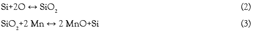
Table 3 shows that the values of the Ti, Oxygen, Mn, Si contains were (1.09%, 4.84%, 9.93% and 3.51%) respectivey, for the welding specimen without TiO2 NPs. as shown in Figures 8 and 9.
| Elt | Line | Int | Error | K | Kr | Wt % |
|---|---|---|---|---|---|---|
| C | Ka | 68.5 | 142.184 | 0.0155 | 0.0138 | 5.24 |
| O | Ka | 133.1 | 142.184 | 0.0306 | 0.0272 | 4.84 |
| Si | Ka | 103 | 228.8563 | 0.0256 | 0.0227 | 3.51 |
| Ti | La | 44 | 144.3423 | 0.0101 | 0.0082 | 1.09 |
| Mn | La | 426.5 | 142.184 | 0.0989 | 0.0878 | 9.93 |
| Fe | Ka | 2572.9 | 2.9738 | 0.8186 | 0.7273 | 75.39 |
| 1 | 0.8884 | 100 |
Table 3: Quantitative results for the (W) welding specimen.

Figure 8: SEM images of weld specimens (a) W (b, c, d) (S1, S2, and S3) specimens respectively.

Figure 9: EDS analysis for the (W) welding specimen.
Table 4 shows that the values of the Ti, Oxygen, Mn, Si contains were (1.27%, 11.86%, 8.56% and 3.06%) respectivey, for the welding specimen with 2% TiO2 NPs as shown in Figure 10.
| Elt | Line | Int | Error | K | Kr | Wt % |
|---|---|---|---|---|---|---|
| C | Ka | 115.4 | 144.3423 | 0.0263 | 0.0213 | 7.84 |
| O | Ka | 343.6 | 144.3423 | 0.0794 | 0.0643 | 11.86 |
| Si | Ka | 82.1 | 205.309 | 0.029 | 0.0234 | 3.06 |
| Ti | La | 49.6 | 143.8454 | 0.0113 | 0.0096 | 1.27 |
| Mn | La | 326.7 | 144.3423 | 0.0761 | 0.0616 | 8.56 |
| Fe | Ka | 2437.4 | 2.9474 | 0.7791 | 0.6305 | 67.41 |
| 1 | 0.8093 | 100 |
Table 4: Quantitative results for the (S3) welding specimen.

Figure 10: EDS analysis for the (S3) welding specimen.
Conclusion
The effect of adding of TiO2 NPs colloidal to weld joints welded by wire electrode E6013 in arc welding method had been investigated. The Impact toughness, and microstructure of samples had been studied.
• With the adding of TiO2 NPs colloidal to the welding joints, there was an increase in Impact toughness for welding area about (42%) at adding ratio of TiO2 of (1.5%)
• Increasing the ratio of TiO2 NPs in welding joints above (1.5%) due to decrease in impact toughness. This is due to the increasing in the presenence ratio of oxygen.
• With the adding of TiO2 NPs colloidal to the welding joints, there was an increase in Ti contain and a decrease in Mn, Si contain, led to an increase in quantity of acicular ferritethat lead to reduce the size of grains .
• The grain size of the welding area by wire electrode (E6013) with adding of TiO2 NPs was decreased.
• The SEM test, showed that increasing the content of titanium oxide led to the conversion of columnar zones from Widmanstätten ferrite and allotriomorphic ferrite to fine intragranular ferrite and refining the ferrite grain size of reheated zones.
Declarations
• Avaibility of data and materials
The results of data and materials presented clearly in manuscript but im not permission to present the data in manuscript as my co-authors refused that.
• Competing interests
Our manuscript have no competing interest (finintial and non-financial).
• Funding
We complete our manuscript without any funding, and spend on the manuscript from our money.
• Author contributions
The contribution for authors in manuscript were equaly disributed among three authors.
Acknowledgements
The authors would like to acknowledge the assistance offered by Nanotechnology and Advanced Materials Research Unit (NAMRU) and Laboratories of Mechanical Engineering, Department at Faculty of Engineering, University of Kufa/Iraq and the authors are thankful the Mechanical Workshop in Kufa Cement Plant/ Iraq.
REFERENCES
- Zhang R, Gao L. Effect of peptization on phase transformation of TiO2 nanoparticles. Mater Res. 2001;36:1957-1965.
- Ang JY, Mei S, Ferreira JM. Hydrothermal synthesis of nanosized titania powders: Influence of tetraalkyl ammonium hydroxides on particle characteristics. J Am Ceram Soc. 2001;84:1696-1702.
- Wetzel B, Rosso P, Haupert F, Friedrich K. Epoxy nanocomposites–Fracture and toughening mechanisms. Eng Fract Mech. 2006;73:2375-2398.
- Nedjad SH, Farzaneh A. Formation of fine intragranular ferrite in cast plain carbon steel inoculated by titanium oxide nanopowder. Scr Mater. 2007;57:937-940.
- Kiviö M, Holappa L, Iung T. Addition of dispersoid titanium oxide inclusions in steel and their influence on grain refinement. Metall Mater Trans B. 2010; 41:1194-1204.
- St Laurent S, L'Espérance G. Effects of chemistry, density and size distribution of inclusions on the nucleation of acicular ferrite of C-Mn steel shielded-metal-arc-welding weldments. Mater Sci Eng A. 1992;149:203-216.
- Zhang D, Terasaki H, Komizo YI. In situ observation of the formation of intragranular acicular ferrite at non-metallic inclusions in C–Mn steel. Acta Mater. 2010;58:1369-1378.
- Byun JS, Shim JH, Suh JY, Oh YJ, Cho YW, Shim JD, et al. Inoculated acicular ferrite microstructure and mechanical properties. Mater Sci Eng: A. 2001;319:326-331.
- Byun JS, Shim JH, Cho YW. Influence of Mn on microstructural evolution in Ti-killed C–Mn steel. Scr Mater. 2003;48:449-454.
- Gianetto JA, Smith NJ, McGrath JT, Bowker JT. Effect of composition and energy input on structure and properties of high-strength weld metals. New York, NY, USA. 1992;71:407-s.
- Babu SS. The mechanism of acicular ferrite in weld deposits. Curr Opin Solid St M. 2004;8:267-278.
- Gourgues AF, Flower HM, Lindley TC. Electron backscattering diffraction study of acicular ferrite, bainite, and martensite steel microstructures. J Mater Sci Technol. 2000;16:26-40.
- Diaz-Fuentes M, Iza-Mendia A, Gutierrez I. Analysis of different acicular ferrite microstructures in low-carbon steels by electron backscattered diffraction. Study of their toughness behavior. Metallurgical and Materials Transactions A. 2003;34:2505-2516.
- Fattahi M, Nabhani N, Vaezi MR, Rahimi E. Improvement of impact toughness of AWS E6010 weld metal by adding TiO2 nanoparticles to the electrode coating. Mat Sci Eng. A. 2011;528:8031-8039.
- Pal TK, Maity UK. Effect of nano size TiO2 particles on mechanical properties of AWS E11018M type electrode. Mater Sci Appl. 2011;2:1285.
- AWS board of directors. Specification for carbon steel electrodes for shielded metal arc welding. American National standards institute. 2004.
- American A, Standard N. Standard methods for mechanical testing of welds. 2007.
- Diaz-Fuentes M, Iza-Mendia A, Gutierrez I. Analysis of different acicular ferrite microstructures in low-carbon steels by electron backscattered diffraction. Study of their toughness behavior. Metall Mater Trans A. 2003;34:2505-2516.
- Ramkumar KR, Natarajan S. Investigations on microstructure and mechanical properties of TiO2 Nanoparticles addition in Al 3003 alloy joints by gas tungsten arc welding. Mater Sci Eng: A. 2018;727:51-60.
- Roy J, Rai RN, Saha SC. Effect of TiO2 enriched fluxes on the bead geometry, grain size and hardness in submerged arc welds. Int J Mater Prod Tec. 2018;56:313-325.
- Grong O, Siewert TA, Martins GP, Olson DL. A model for the silicon-manganese deoxidation of steel weld metals. Metall Mater Trans A. 1986;17:1797-1807.
Citation: Al-Obaid AF, Yasir AS, Thahab SM (2020) Improving Impact Toughness for Welding Joints of Steel by Adding TiO2 Nanoparticales. J Appl Mech Eng. 9:323. doi: 10.35248/2168-9873.20.9.323
Copyright: © 2020 Al-Obaid AF, et al. This is an open access article distributed under the term of the Creative Commons Attribution License, which permits unrestricted use, distribution, and reproduction in any medium, provided the original author and source are credited.