

Indexed In
- Genamics JournalSeek
- JournalTOCs
- CiteFactor
- RefSeek
- Hamdard University
- EBSCO A-Z
- OCLC- WorldCat
- Publons
- Google Scholar
Useful Links
Share This Page
Journal Flyer
Open Access Journals
- Agri and Aquaculture
- Biochemistry
- Bioinformatics & Systems Biology
- Business & Management
- Chemistry
- Clinical Sciences
- Engineering
- Food & Nutrition
- General Science
- Genetics & Molecular Biology
- Immunology & Microbiology
- Medical Sciences
- Neuroscience & Psychology
- Nursing & Health Care
- Pharmaceutical Sciences
Review Article - (2021) Volume 10, Issue 10
The Performance of Gear with Backlash: A Review
Getachew Admassie Ambaye*Received: 09-Aug-2021 Published: 08-Oct-2021, DOI: 10.35248/2168-9873.21.10.389
Abstract
As the service time of the gear increases, its tooth profile could be deviated from its initial design shape and size as a result of time-varying load, overheating, wear, friction, and other working environmental impacts. Gear backlash is one of the non-linear parameters of the gear that adversely affects the performance of the transmission system. Backlash can be introduced deliberately for lubrication and free paly purposes or due to the gear tooth wear (reduction of the gear tooth thickness). The objective of this paper is to review and encapsulate this literature to provide a wide and good reference for scholars to be utilized. Assessing the effect of backlash on the dynamics and flash temperature of the gear is the main target of this review paper.
Keywords
Backlash; Sliding motion, Tooth profile modification; Flash temperature; Bulk temperature
Introduction
Gears play a vital role in the mechanical power transmission system. They are employed to reduce or multiply the torque for different applications. Their life will be determined due to different factors, such as wear, backlash, and amount of load, thermal load, and fluctuation of the load. These factors have an effect on the dynamic characteristics of the gearboxes which in turn directly influences the performance of the system.
Gears may fail due to different internal and external excitations. The most frequent mode of failure is fatigue, followed by impact (tensile or shear), and wear (abrasive or adhesive). In an analysis of over 1500 studies, the three most frequent gear failure modes were identified to be tooth bending fatigue – 32%, tooth bending impact – 12 ½%, and abrasive tooth wear – 10% [1]. Non-smooth nonlinearities such as backlash, dead-zone, component failure, friction, hysteresis, saturation and time delays are common in industrial control systems. Backlash is a dynamic characteristic that exists in mechanical couplings such as gear trains, and always limits the accuracy of servomechanisms and other mechanical power transmission systems. Dead zone is a static input-output relationship which for a range of input values gives no output; it also limits system performance. Dead zone characteristics are often present in amplifiers, motors, hydraulic valves and even in biomedical actuation systems [2].
Backlash is the gap between gears tooth at the pitch circles. This distance can be involved in the gears either deliberately or without any intention due to the manufacturing error and assembly fault.
Backlash is provided deliberately for a different reason and cannot be designated without consideration of machining conditions. The general purpose of backlash is to prevent gears from jamming by making contact on both sides of their teeth simultaneously. It’s also introduced intentionally for lubricant space and differential expansion between the gear components and the housing.
Backlash is built into speed reducers to let the gears mesh without binding and to provide space for an oil film between the teeth. This prevents overheating and tooth damage. On the other hand, if the same clearance causes lost motion between the input and output shafts as a result, it is difficult to achieve an accurate positioning in equip- ment for those machines or elements that need accuracy very importantly like robots, machine tools and measuring instruments. A simple backlash model is shown in Figure 1, which illustrates the fact that when the difference between the motor and the load position is smaller than tan(φ), then the two shafts are disengaged and no torque is applied to the motor or the load [3]. The basic purpose of designing backlash is to prevent locking the gears, as well as to prevent coming into contact on both sides of one tooth simultaneously. A small amount of backlash is desirable to make the necessary gap for lubrication and partially expansion of gears. Also, the amount of backlash should not be increased exceedingly, because the backlash causes high manufacturing costs [3].

Figure 1: Illustration of backlash.
Backlash can be introduced in two ways; (1) by reducing the thickness of the gear and (2) by modifying the center distance between the gear mates. Backlash due to tooth thickness change is typically measured along the pitch circle. In this case, either one or both of the gear mate thickness will be reduced from the designed value. Figure 2a shows the left side of the gear whose thickness is reduced. The backlash due to this effect can be expressed as follow:

Figure 2: Backlash due to (a) tooth thickness modification and (b) Center distance modification.
φ = ti − tb (1)
The second way to introduce backlash in gear is by modifying the center distance of the gear, in this case, there is no contact between pitch circles of the two gears. The contact of the gear teeth exists on the addendum. The backlash that is created due to modified center distance is shown in Figure 2b. The thickness of the gear tooth will decrease from the pitch circle to the top face of the gear. So, there will be a gap between these teeth again, and this can be expressed as follows.
Φ = 2(Δc)ana (2)
According to ISO/TR 10064-2-1996 [4], the value of minimum backlash can be ex- pressed in Equation 3. Therefore, the gear mates should have at least a minimum back- lash value, but the too large backlash will have another problem on the gear such as the impact of the gear and vibration.
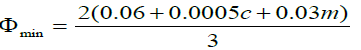 (3)
(3)
Backlash affects the dynamics of the system because it disturbs the smooth operation of the system. Prajapat GP, et al. [5] investigated the effect of backlash on the doubly-fed induction generator based wind turbine. A small amount of backlash is recommended for smooth operations. If an un-optimized amount of backlash is involved with gears then the smooth operation will be affected. In addition to this, the backlash affects the wear rate of the gear surfaces. Pitting wear is one of the prominent types of wear that repeatedly occurs on gears. It is the surface failure of the gear material as a result of stress developed that exceeds the endurance or fatigue limit of the material. Ghazaly N, et al. [6] investigated the influence of shaft misalignment and backlash on the stress generated on the spur gear using FEM. They conclude when the misalignment angle increases the deformation will increase, while the stress generated at contact and root areas decreases. Scuffing or scoring is a failure mode of gears when there is direct contact between the gear mates [7]. To prevent these contacts some small gaps or backlash should be provided initially so that the lubricant will have space to separate a direct asperity to asperity contacts of the gear mates. Many researchers have done a lot on it, and the minimum oil film thickness should be revealed to enhance the performance of the gear. When the gears are in contact, only a certain portion of the surface area will be in contact. The gears without the load have a line contact but when the load increases this line will change into a small area. The machine elements such as spherical bearings and gears have elliptical contact [8]. Gear systems or gear trains tend to play a very vital role in all industries and our day-to-day life, any failure to the gear system leads to total system failure. Pitting and tooth breakage is the most mode of failures of the gear. Pitting is a major cause of gear failure accounting for nearly 60% of the gear failures [9]. Pitting is the formation of craters on the gear tooth surface. These craters are formed due to the high amount of compressive contact stresses in the gear surface occurring during transmission of the torque or in simple terms due to compressive fa- tigue on the gear tooth surface [10]. Pitting and scuffing of a gear tooth appearance are shown in Figure 3.

Figure 3: Gear tooth surface (a) pitting and (b) spall [7].
Liang X, et al. [10] reviewed on dynamic modeling of a gearbox fault and they mention that gear tooth pitting is the most common failure mode of gears. The main cause of tooth pitting or spalling which is a large pit formed when the pits are joined together are subsurface cracks caused by foreign or inclusions in the gear materials, metal to metal contact of asperities, or defects due to low lubricant film thickness and foreign particle contamination of the lubricant.
Metal to metal contacts will occur when the oil film is broken; the reason for oil film breaking is low viscosity of the lubricant at the beginning or high flash temperature of the gear. The high temperature will reduce the viscosity of the lubricant and then when the gear rotates it will splash easily and break down. Therefore, pitting will occur. Conjugate action of gear teeth in mesh consists primarily of sliding and rolling motions. At the pitch line, sliding velocity is zero; however, sliding velocity increases when the conjugated tooth contact line travels away from the pitch line in both directions. Heat is generated by sliding friction of tooth surfaces. The temperature distribution is proportional to the distribution of contact pressure and sliding velocity. Taburdagitan M, et al. [11] studied the determination of surface temperature rise with thermo elastic analysis of spur gears, and they found that the surface temperature rises on spur gear teeth pair along the pressure line are highest at the very beginning of the meshing and the surface temperatures at the initial contacts can be decreased by profile modification at the tip of the tooth. The low contact temperature of the optimized design can significantly contribute to preventing tooth surface damage under “nolubricant” operating conditions was done by Wink CH, et al. [12].
In this paper, the research review has been made by categorizing into two parts,
(1) Research review on the effect and advantages of the backlash of the gear and (2) research review on the flash temperature of the gear. The reviews are presented in the following subsections.
Research Review
The backlash of the gear
In industrial drives, elements like gearboxes and flexible couplings introduce back- lash. For instance, a commonly used flexible coupling gives a backlash of about 10 degrees that can be partly filled with rubber [2]. Papageorgiou D, et al. [3] estimated the backlash for the industrial drivetrain system. Backlash plays an important function in many systems and it is one of the most important nonlinearities that limit the performance of speed and position control in industrial, robotics, automotive, automation, and other applications [13].
Observing the effect of backlash on friction, Lichtsinder A, et al. [14] concluded that when the backlash gap is decreased by mechanical means, friction is generally increased, and vice versa. Hence, there is a lower bound to all possible friction- backlash combinations defining a Feasibility Area. The gear transmission system is one of the most important components of the mechanical system. Gear systems are widely used in various power transmission applications due to their distinguished merits of the accurate transmission ratio, large power range, high transmission efficiency and stable operation quality [15,16]. Lagerber A, et al. [17] conducted experimental validation for backlash estimation in the automotive power train. Merzouki R, et al. [18] did the same thing to estimate the backlash for electromechanical actuators. Ravanbod-Shirazi L, et al. [19] proposed a new approach for estimating the backlash amplitude, characterized by dead zone model identification is achieved in two main steps. In the first step, a pre- estimation of the backlash amplitude is performed based on the existing physical relation between the amplitude of the backlash, instant of commutation, the motor and the load speeds. In the second step, a least-square criterion based on the model of the motor speed (nonlinear regression model) is minimized around the pre-estimation. The comparison between the backlash identification made by this approach and an approach that doesn’t use the pre-estimation illustrates that the first method is considered advantageous.
Nordin M, et al. [2] proposed a new model for an inertia free elastic shaft with internal damping connected to a backlash. They found that the new model gives a negligible torque error in comparison with the exact torque solution. Dyaneshwar S, et al. [20] studied the effect of backlash on bending stresses in spur gears. They found that as the backlash increases the maximum von Mises stress increases slightly initially and after that, it increases very much and after that, it nearly remains constant. Also, the maximum deflection is nearly proportional to the backlash. Ambaye AG, et al. [21] investigated the effect of backlash on the dynamics of the spur gear using MC ADAMS software. They fund that the angular acceleration of the gear decreases as the load imposed on the gear increases. This shows that, though two gears have the size of backlash, their vibration level is a function of the size of the imposed load. In addition, the contact force components of the gear along the tangential and radial direction increased slightly as the backlash increased.
Ambaye AG, et al. [22] analysed the nonlinear oscillations in spur gear pairs with approximated modeling of backlash nonlinearity.
Backlash is included as a displacement-type nonlinear function and approximated with a third-order polynomial of DTE as a cubic nonlinearity. Moradi H, et al. [23] investigated how the backlash affects the performance of the gears based on the factorial theory. In order to get a reasonable and precise dynamic analytic result, the fractal theory is employed here to express the backlash instead of the existed way of setting backlash as a fixed value or a steady random number that meets the normal distribution.
Three methods of gear backlash evaluation, i.e (1) fractal, (2) fixed value and (3) normal distribution methods were compared and clearly concluded that the fractal method is more effective and reasonable than the latter two ways because they both have the shortcoming of missing to reflect the influence by the changing backlash. Therefore, the normal distribution method can’t get the unique answer when the average backlash is set, while the fractal method doesn’t have these drawbacks.
Chen Q, et al. [24] developed an algorithm to minimize or eliminate the effect of back- lash on the accuracy of the motion of the gear. The algorithm is formulated using a rotating coordinate system and can produce backlash-free motions for a wide range of geometrical paths including those with very sharp edges. Lotfi B, et al. [25] investigated the dynamics of a two-stage gear system involving backlash and time dependent mesh stiffness. Gear contact is characterized by a periodically changing stiffness and a backlash which can lead to loss of the contact. The nonlinear dynamic response of the system is studied using a linearization technique, which decomposes the nonlinear system into some linear systems satisfying some conditions. For low rotational speeds, the system is characterized by a discontinuity of movement which is due to the discontinuous transfer of the kinetic energy from the input wheel to the output receiving wheel. V¨or¨os
Walha L, et al. [26] developed a new analytic form of backlash characteristic description. The backlash parameters in the model equation are separated; hence their estimation can be solved as a quasi-linear problem using an iterative method with internal variable estimation. Also, the identification of cascaded systems consisting of an input backlash followed by a linear dynamic system is presented. Simulation studies of backlash and cascaded systems identification are included. J Voros [27] studied the torsional vibrations of wind turbine gearbox having two planetary gear stages and one parallel gear stage. The nonlinear dynamic model developed considers factors such as time-varying mesh stiffness, damping, and static transmission error and gear backlash. Dynamic responses of internal components in the gearbox were predicted with the variations of factors such as the Static Transmission Error (STE), mean-to-alternating force ratio and mesh stiffness ratio, adjusted for parametric studies. The increase of the external excitation fluctuation would lead to a large magnitude variation for gearbox components. In addition, compared to the static transmission error, the mesh stiffness was found to have more effect on the torsional vibrations of gearbox components. This is because an increase of the fluctuating mesh stiffness could change the dynamic responses significantly.
Zhao M, et al. [28] developed the newest designs of worm gear drives which allow us to adjust or decrease the amount of backlash. Results of numerical research performed with the finite element method and also the results of experimental research on the innovative worm gear drive with an axially adaptive worm.
The results analysis has led to the conclusion that the described solutions allow reduction of backlash to percent, an even greater reduction of its standard deviation – that is 5 – 10 % of their initial values. Kacalak W, et al. [29] concluded that the reduction of gear rattle noise level can be achieved by avoiding meshing impacts, e.g. by minimizing the traction coefficient of the gear oil or high lubrication film thickness at the gear mesh. In addition to this Fernandez Del Rincon et al. [31] showed the effect of lubricant entrance in the contact area plays a decisive role in the dynamic behaviour. An experiment was also conducted on helical gear pairs from an automotive gearbox in the “idle gear rattle” condition by varying the lubrication mechanism by Russo R, et al. [32] to reveal the effect of lubrication on gear rattling.
The flash temperature of the gear
Friction will occur when two or more bodies come in contact and having a relative motion. Friction can be generated due to different mechanisms such as when one body tries to make sliding, pure rolling, or rolling/sliding motion over the other. The mechanical energy due to the friction will be converted to heat energy and this cause increasing the temperature of the bodies that are in dynamic motion. Kennedy Jr FE, et al. [33] investigated that almost 95% of energy dissipation occurs due to friction that has 5 μm roughness amplitude. When there is a substantial sliding between lubricated rolling gears, excessive temperature will be generated and this in turn breaks down the oil film. After that, the asperities of the rolling elements or gear will come in contact and then if they cannot carry the load they will be deformed plastically. This will facilitate the wear and the wear rate becomes rapid as the load continuously increases. This kind of phenomenon is called scuffing, and the best possible way remedy this failure is just minimizing the working temperature as well as the flash temperature of the rolling bodies. Townsend DP, et al. [34] shows that the gear can fail by scuffing at the tip and root areas of gear by taking a medium hardened spur gear. There is a sliding motion at the tip and roots of gears rather than having a rolling motion, there is high friction at those locations and then the temperature will rise and the oil film thickness will break down then the gear will fail by scuffing.
Srirattayawong S, et al. [35] studied the surface roughness effects on the fluid flow between two rotating cylinders, and they concluded that thermal effects play an important role in the viscosity of the lubricant, as the viscosity decreases when the temperature increases. In addition, the influence of surface roughness is increased when the temperature increases due to the reduction in viscosity. Li S, et al. [36] investigated the effect of load, surface roughness, lubricant viscosity on the flash temperature. Based on their results they concluded that the flash temperature will increase as the torque increase. In addition, the vibration motion also influences the flash temperature not only on Line of Action (LOA), it also affects Out of Line of Action (OLOA). Wang Y, et al. [37] developed a computer analysis of involute spur gear to anticipate the variation of dynamic load, surface temperature and lubricant film thickness along the line of action when the gear tooth has meshed. They didn’t couple the above analysis together, rather they analysed the dynamic load analysis independently and oil film thickness, flash temperature, bulk temperature are done by an iterative method. Elasto Hydrodynamic Lubrication (EHL) can be defined as a form of hydrodynamic lubrication where the elastic deformation of the contacting bodies and the changes of viscosity with pressure play fundamental roles. A substantial amount of work was devoted to resolving elasto hydrodynamics and the first realistic model which provided an albeit approximate solution for elastohydrodynamic film thickness was proposed by Ertel and Grubin. Hua and his colleges investigated the effect of gear ratio and module on the film thick- ness and pressure of the gear by employing EHL theory. They concluded that as the gear ratio increase, the central oil film thickness increases markedly at the recess end, but they found that there is only a very small reduction at the approach end. In addition, if the module is doubled without changing the gear size, the oil film thickness would decrease slightly at the recess end of the gear [37].
Surface conjunction temperature is the temperature at the interface of two contact and mutually sliding solid objects. For any specific part of the sliding surface, frictional temperature rises are very short duration and the temperature generated is called flash temperature, it was originally formulated by Blok in 1937 and developed further by Jaeger in 1944 and Archard in 1958. According to Blok, Jaeger and Archard’s theory, the flash temperature is the temperature rise above the temperature of the solids entering the contact which is called the bulk temperature. The maximum contact temperature ( ) is the sum of bulk temperature (T) and maximum flash temperature (Tf max) expressed as:
Tc = T + Tf max (4)
Depending on the velocities of the rotating elements or gears the flash temperature will be calculated in different equations. A nondimensional measure of the speed at which the ‘heat source’ moves across the surface called the ‘Peclet number’ has been introduced as a criterion allowing the differentiation between various speed regimes. The Peclet number is an indicator of the heat penetration into the bulk of the contacting solid, i.e. it describes whether there is sufficient time for the surface temperature distribution of the contact to diffuse into the stationary solid. A higher Peclet number indicates a higher surface velocity for constant material characteristics. Flash temperature equations are given in terms of the heat supply over the contact area, the velocity, and the thermal properties of the material. They are applicable in many practical cases such as gears, roller bearings, cutting tools and others.
The critical surface temperature of the gear for scoring lies between 443 K and 447 K under the conditions of tooth material and lubricant used. The scoring resistance of gears can be accurately estimated by evaluating the critical surface temperature. Scoring resistance of the gear may be affected by the quantity of lubricant, thermal and mechanical properties of the gear material, geometrical errors and surface roughness of the gear, and dynamic load. Abel PB, et al. [38] have researched the effect of tooth profile modification of the scoring resistance of spur gears, and they draw the following conclusions:
• Small modification of addendum will significantly affect the scoring resistance of the gear.
• The scoring resistance of gears can be accurately estimated by evaluating the critical surface temperature.
Dhanasekaran S, et al. [40] conducted research on gear tooth wear in sintered spur gears under dry running conditions, they revealed that the maximum wear has occurred in the dedendum and addendum regions even though the gear wear depends on the material hardness and strength of the gear material. In addition, Walton D and Walton D, et al. [41] also work on the wear of unlubricated metallic spur gear and they draw the following conclusion, temperature measurements of the gear bulk body revealed an almost linear increase with speed up to about 500 rev/ min, where the temperatures of the driver and driven were almost equal.
A 2D coupled thermoselastic analysis has been carried out by Taburdagitan M, et al. [11], to investigate the tooth surface temperature rise of the spur gears. They consider heat generation from the contact tooth pairs in addition to load sharing between contacting tooth pairs and elastic deformation. As the friction coefficient and load increase, the tooth contact also increases so that the tooth surface scuffing will be highly probably caused by high tooth contact temperature [42]. To minimize the contact temperature either the load or frictional coefficient should be minimized, when the gear is subjected to a high load the frictional coefficient should be minimized. Dong HL, et al. [43] Studied on temperature analysis of involute gear based on mixed elastohydrodynamic lubrication theory considering tribodynamic behaviors. They concluded that the surface of the pinion has a higher temperature in the approaching stage compared with that of the wheel while this is reversed after the pitch point and the temperatures at two ends of the gear tooth width are obviously higher than that in the middle part due to the stress concentration. The film temperature in the mid-layer is much higher than the temperature on the surfaces. For heavy-load gear systems, the temperature of the film center is much higher than that of two boundaries. The temperature of the boundary increases until close to the outlet and then slightly decreases. The distribution of maxi- mum flash temperature and minimum film thickness is respective consistent with that of Blok flash temperature and thickness of Dowson in the meshing cycle. The flash temperature from transient thermal elastohydrodynamic lubrication, TEHL is higher in the dedendum region and lower in the addendum region compared to that from Blok theory [8,44-45].
Luo B, et al. [46] studied the influence factors on the bulk temperature field of gear using parametric design APDL. Tooth profile modification will affect the distribution of the bulk temperature field; therefore, the bulk temperature can be reduced by the tooth profile modification in addition to this they also conclude that the initial temperature of the lubricant oil will determine the bulk temperature.
If the initial temperature of the lubricant is high, then the bulk temperature of the gear also high. This concept is supported by, Taburdagitan M, et al. [11] conducted an experiment and numerical analysis of spur gear, they saw that the numerical results found by FEA are relatively higher than that of the experimental results. This is because splashing lubricated conditions and the coefficient of friction may not be constant as an assumed constant in the FEA.
Conclusion
In this paper, the performances of gear related to the backlash have been reviewed. Backlash is important for the smooth operation of gears. In addition, gear life is limited due to loading and operational conditions. When the gear pairs transmit a load the heat is generated due to friction, and this heat alters the material property of the gear mates, the pitting and scuffing will occur during this time and the gear tooth faces is worn out.
The gear should be designed with optimum backlashes and tooth profile should be manufactured based on the design. Assembly error should be minimized or removed be- cause the assembly error may cause an unwanted backlash due to deviation of center distance where it is supposed to be. In addition, when the gear tooth faces are worn out it should be removed immediately because the transmission error is increased drastically, this will cause severe vibration and failure of the components that mounted on it or the mechanical elements found nearby.
REFERENCES
- Alban LE, editor. Systematic analysis of gear failures. ASM International; 1985.
- Nordin M, Bodin P, Gutman PO. New models and identification methods for backlash and gear play. InAdaptive Control of Nonsmooth Dynamic Systems. Springer, London.2001;1-30.
- Papageorgiou D, Blanke M, Niemann HH,Richter JH. Backlash estimation for industrial drive-train systems, IFAC-Papers-OnLine. 2017;50(1):3281–3286.
- Wojtyła M, Jakubiec W, Płowucha W. Comparison ISO standards. 1328-1: 1995.
- Prajapat GP, Senroy N, Kar IN. Modeling and impact of gear train backlash on performance of DFIG wind turbine system. Electr Power Syst Res. 2018;163:356-364.
- Ghazaly N, Kamel A, Mousa MO. Influence of misalignment and backlash on spur gear using fem. Int J Mech Prod Eng. 2014;2(12):2320-2392.
- Gear failures. Available: www.machinedesign.com/news/recognizing-gear fail- ures.
- Stachowiak GW, Batchelor AW. Engineering tribology. Butterworth-heinemann. 2013;16.
- Kkaarthic. Failure modes in gears, causes of failure of gears, gears failure.
- Liang X, Zuo MJ, Feng Z. Dynamic modeling of gearbox faults: A review. Mech Syst Signal Process. 2018;98:852-876.
- Taburdagitan M, Akkok M. Determination of surface temperature rise with thermo-elastic analysis of spur gears. Wear. 2006;261(5-6):656-665.
- Wink CH, Mantri NS. AGMA Technical Paper.2012.
- Nordin M, Gutman PO. Controlling mechanical systems with backlash—a survey. Automatica. 2002;38(10):1633-1649.
- Lichtsinder A, Gutman PO. Backlash and Friction Reciprocal Effect on Limit Cycle Existence. IFAC Proceedings Volumes. 2009;42(6):249-254.
- Li W, Liu B. Experimental investigation on the effect of shot peening on contact fatigue strength for carburized and quenched gears. Int J Fatigue. 2018;106:103-113.
- Liu X, Yang Y, Zhang J. Investigation on coupling effects between surface wear and dynamics in a spur gear system. Tribol Int. 2016;101:383-394.
- Lagerberg A, Egardt B. Estimation of backlash in automotive powertrains—an experimental validation. IFAC Proceedings Volumes. 2004;37(22):47-52.
- Merzouki R, Cadiou JC. Estimation of backlash phenomenon in the electromechanical actuator. Control Eng Pract. 2005;13(8):973-983.
- Ravanbod-Shirazi L, Besancon-Voda A. Backlash identification: a two-step approach. IFAC Proceedings Volumes. 2002;35(1):85-90.
- Dyaneshwar S, Prof Mangrulkar K S, Effect of backlash on bending stresses in spur gears.2016;1(7).
- Ambaye GA, Lemu HG. Dynamic analysis of spur gear with backlash using ADAMS. Materials Today: Proceedings. 2021;38:2959-2967
- Ambaye, Getachew A, Hirpa G L: Effect of Backlash on Transmission Error and Time Varying Mesh Stiffness. In International Workshop of Advanced Manufacturing and Auto- mation, Springer, Singapore. 2020; 18-28.
- Moradi H, Salarieh H. Analysis of nonlinear oscillations in spur gear pairs with approximated modelling of backlash nonlinearity. Mech Mach Theory. 2012;51:14-31.
- Chen Q, Ma Y, Huang S, Zhai H. Research on gears’ dynamic performance influenced by gear backlash based on fractal theory. Appl Surf Sci. 2014;(313):325-332.
- Lotfi B, Zhong ZW, Khoo LP. A novel algorithm to generate backlash-free motions. Mech Mach Theory. 2010;45(8):1171-1184.
- Walha L, Fakhfakh T, Haddar M. Nonlinear dynamics of a two-stage gear system with mesh stiffness fluctuation, bearing flexibility and backlash. Mech Mach Theory. 2009;44(5):1058-1069.
- J Voros: Identification of cascade systems with backlash, Int J Control. 2010; 83(6):1117–1124.
- Zhao M, Ji JC. Nonlinear torsional vibrations of a wind turbine gearbox. Appl Math Model. 2015;39(16):4928-4950.
- Kacalak W, Majewski M, Budniak Z. Innovative design of non-backlash worm gear drives. Arch Civ Mech Eng. 2018;18(3):983-999.
- Baumann A, Bertsche B. Experimental study on transmission rattle noise behaviour with particular regard to lubricating oil. J Sound Vib. 2015;(341):195-205.
- Fernandez-Del-Rincon A, Diez-Ibarbia A, Theodossiades S. Gear transmission rattle: Assessment of meshing forces under hydrodynamic lubrication. Appl Acoust. 2019;(144):85-95.
- Russo R, Brancati R, Rocca E. Experimental investigations about the influence of oil lubricant between teeth on the gear rattle phenomenon. J Sound Vib. 2009;321(3-5):647-661.
- Kennedy Jr FE, Karpe SA. Thermocracking of a mechanical face seal. Wear. 1982;79(1):21-36.
- Townsend DP. Dudley's Gear handbook: The Design, Manufacture, and Application of Gears. McGraw-Hill, Inc., Dudley's Gear Handbook: the Design, Manufacture, and Application of Gears. Second Edition(USA), 1991, Chapters paged separately, 6 x 9 in., Illustrated, 1991. 1991.
- Srirattayawong S, Gao S. Surface roughness effects on fluid flow between two rotating cylinders. Inky Eng Mat.Trans Tech Publications Ltd. 2015;(642): 275-280.
- Li, S. and Amdlnisetti, A.: On the flash temperature of gear contacts under the tribo-dynamic condition, Tribol Int,2016; (97);6–13.
- Wang Y, Tang W, Chen Y, Wang T, Li G, et al. Investigation into the meshing friction heat generation and transient thermal characteristics of spiral bevel gears. Appl Therm Eng. 2017;(119):245-253.
- Abel PB, Ferrante J, Bhushan B. Surface physics in tribology. Modern Tribology Handbook (Editor: Bhushan, B). 2001:5.
- Terauchi Y. and Nadano H. Effect of tooth profile modification on the scoring resistance of spur gears, Wear.1982;80(1): 27–41.
- Dhanasekaran S, Gnanamoorthy R. Gear tooth wear in sintered spur gears under dry running conditions. Wear. 2008;265(1-2):81-87.
- Walton D, Goodwin AJ. The wear of unlubricated metallic spur gears. Wear. 1998;222(2):103-113.
- Gou X, Zhu L, Qi C. Nonlinear dynamic model of a gear-rotor-bearing system considering the flash temperature. J Sound Vib. 2017;(410):187-208.
- Dong HL, Hu JB, Li XY. Temperature analysis of involute gear based on mixed elastohydrodynamic lubrication theory considering tribo-dynamic behaviors. J Tribol. 2014;136(2).
- Xue JH, Li W, Qin C. The scuffing load capacity of involute spur gear systems based on dynamic loads and transient thermal elastohydrodynamic lubrication. Tribol Int. 2014;79:74-83.
- Bobach L, Beilicke R, Bartel D, Deters L. Thermal elastohydrodynamic simulation of involute spur gears incorporating mixed friction. Tribol Int. 2012;48:191-206.
- Luo B, Li W. Influence factors on bulk temperature field of gear. Proceedings of the Institution of Mechanical Engineers, Part J J eng tribol. 2017;231(8):953-964.
Citation: Ambaye AG (2021) The Performance of Gear with Backlash: A Review. J App Mech Eng 10:389
Copyright: © 2021 Ambaye AG. This is an open access article distributed under the term of the Creative Commons Attribution License, which permits unrestricted use, distribution, and reproduction in any medium, provided the original author and source are credited.