
Indexed In
- Open J Gate
- Genamics JournalSeek
- JournalTOCs
- China National Knowledge Infrastructure (CNKI)
- Electronic Journals Library
- RefSeek
- Hamdard University
- EBSCO A-Z
- OCLC- WorldCat
- SWB online catalog
- Virtual Library of Biology (vifabio)
- Publons
- MIAR
- Euro Pub
- Google Scholar
Useful Links
Share This Page
Journal Flyer

Open Access Journals
- Agri and Aquaculture
- Biochemistry
- Bioinformatics & Systems Biology
- Business & Management
- Chemistry
- Clinical Sciences
- Engineering
- Food & Nutrition
- General Science
- Genetics & Molecular Biology
- Immunology & Microbiology
- Medical Sciences
- Neuroscience & Psychology
- Nursing & Health Care
- Pharmaceutical Sciences
Review - (2020) Volume 11, Issue 1
Technical Feasibility of Using Frac-Packed Wells for Producing Natural Gas from Offshore Gas Hydrate Reservoirs
Xuejun Hou1, Boyun Guo2 and Ellis Ekhator2*2University of Louisiana at Lafayette, Lafayette, Louisiana, USA
Received: 28-Jan-2020 Published: 28-Feb-2020, DOI: 10.35248/2157-7463.19.10.400
Abstract
This paper presents a feasibility analysis of using frac-packing completion techniques to produce natural gas from offshore gas hydrate reservoirs. A case study was carried out for the gas hydrate accumulations in the northern South China Sea. The feasibility analysis covers the requirements of proppant size, fluid injection rate, fracturing pressure, and well productivity. For the median grain size of sediments in the studied formation from 2.60 to 28.96 μm with an average value of 8.49 μm, the required range of proppant size is between 333 mesh to 748 mesh (0.001 inch ~ 0.003 inch). Since the proppants in this size range are not commercially available, it would be economical to use screened natural sands as proppants in frac-packing operations. The minimum flow rate of fracturing fluid required to carry the 0.003 inch proppant/sand into the fracture tip at 510 ft is 3.64 bpm, which is much lower than the practical values ranging from 20 bpm to 100 bpm. Therefore proppant/sand transport during frac-packing is not a concern. To create a horizontal fracture of 510 ft radius with a fracturing fluid injection rate of 72 bpm, the maximum bottom hole injection pressure is predicted to be 2,378 psi, which is only 334 psi above the reservoir pressure and can be handled by most pumps used in frac-packing operations. Well productivity forecast with a simplified mathematical model shows that a commercial gas production rate of 16 MMscf/day is achievable with the fracture radius of 510 ft. However, the model requires further validation.
Keywords
Gas hydrate; Frac-packing; Sand control; Well productivity; Production optimization.
Abbreviations
c: Compressibility in 1/psi; E: Young’s modulus in psi; fF: Fanning friction factor; g: Gravitational acceleration factor (32.17 lbm-ft/lbf-s2); h: Thickness of gas hydrate reservoir in ft; K: Consistency index in cp; kf: Fracture permeability in md; km: Matrix permeability in md; p: Pressure in psia; p ̅: Average reservoir pressure in psia; pd: Pressure drawdown in psia; pe: Pressure at the no-flow boundary in psia; pf :The pressure in the fracture in psia; pF: Wellbore fracturing pressure in psia; pt: Fracture tip pressure in psia; pw: Wellbore pressure in psia; q: Flow rate in the fracture in bpm; qi: Injection rate in bpm; qimin: The minimum required fracturing fluid flow rate in bpm; Q: Gas production rate in ft3/s; QF: Fracture flow rate in ft3/s; Qg: Total gas production rate of gas well in gas hydrate conditions in Mscf/d; r: Fracture propagation radius in ft; R: Radius of the gas hydrate reservoir in ft; Rf: Radius of the fracture in ft; rw: Wellbore radius in ft; T: Formation temperature in °F; v: Velocity in the direction perpendicular to the fracture in ft/s; vsl: The terminal slip velocity in ft/s; V: Volume of a fluid element in ft3; vf: Velocity of the fluid in the fracture in ft/s; w: Average fracture width in inch; wp: The propped fracture width in inch; Vp: The volume of sand/proppant; z: Gas compressibility factor; ρL: Fluid density in lbm/ft3; ν: Poisson’s ratio; μg: Gas viscosity in cp; φ: Reservoir porosity; f : Fracture; sc: Standard condition
Introduction
As natural gas from shale formations becomes a global energy "game-changer," energy researchers are developing new technologies to produce natural gas from offshore hydrate deposits. Because gas hydrate deposits are believed to be a larger hydrocarbon resource than all of the world's oil, natural gas and coal resources combined [1], if these deposits can be efficiently and economically developed, gas hydrate could become the next energy game-changer.
Enormous amounts of offshore gas hydrate have been found beneath Arctic permafrost, beneath Antarctic ice, and in sedimentary deposits along continental margins worldwide. In some parts of the world, they are much closer to highpopulation areas than any natural gas field. These nearby deposits might allow countries that currently import natural gas to become self-sufficient. In the Gulf of Mexico alone there is an estimated mean value of 21,000 TCF of in-place gas hydrates, according to the congressional report by the Congressional Research Service [2]. Even if a fraction of the gas hydrates can be economically produced, it could add substantially to the 1,300 TCF of technically recoverable U.S. conventional natural gas reserves. However, the gas hydrates have no confirmed commercial production to date. The evaluation work of Moridis et al. [3] predicts that gas production from a single horizontal gas hydrate well can reach 6.1 to 33 MMscf per day in the offshore Gulf of Mexico region. Based on the 3D reservoir modeling work done by Gaddipati and Anderson [4], gas production per well can reach 60 to 65 MMscf per day.
The Japan Oil, Gas and Metals National Corporation (JOGMEC) carried out two pilot tests on gas portions from offshore hydrate deposits [5,6]. In the 6-day production process, the total amount of natural gas produced reached approximately 119,500 m3. It was noted that the gas production rate was greater than the expected gas production rate by numerical simulations. However, the well operation was shut-down in three weeks due to sand production and low well productivity. The well production rate dropped to less than 8,000 m3 per day.
China Geological Survey (CGS) carried out a hydrate gas production test in the South China Sea [7,8]. In the consecutive 8-day production, around 1.2 × 10⁵ m3 of natural gas in total was produced from hydrate-bearing sediments, averaged daily output of 1.6 × 10⁴ m3. The production continued two months for a cumulative gas production of 3.09 × 10⁵ m3 and an average daily production of more than 5,150 m3 per day [9,10]. The test production was terminated due to low productivity of well associated with sand production problems.
Producing natural gas from gas-hydrates first requires the destabilization of the in-situ hydrate compound, i.e., destroying the molecular structures of hydrates by depressurization, thermal stimulation, and/or chemical inhibition. These processes also cause the physical destabilization of the hydrate-bearing zones. The gas production trials in Japan [11] and China [12] revealed common inter-related problems of sand production, wellbore collapse, and low well productivity that hinder the extraction process of gas production from offshore gas hydrate deposits. In this study, we investigated the feasibility of using frac-packed wells to solve these problems.
Frac-packing is a mature technology widely used for solving the sand production problems in unconsolidated offshore oil reservoirs [13]. It involves both hydraulic fracturing and injecting proppant into the created fracture. The proppant propps the fracture open and also blocks the sand/fines from the formation. Jennings [14] showed that using larger synthetic proppants in frac-packing can improve well productivity and effectively control formation fines. In Jennings [14] work, several sand and ceramic proppants were tested with three different distributions of formation fines. Testing showed that the packing of sand/proppant allows some invasion of fines, but that most of the fines material accumulates within the first few millimeters of the pack and is not allowed to flow through the column completely. This work is more in line with filtration theory in which most of the proppant pack (filter) is used to capture contaminants (fines), as opposed to merely creating a screen fine enough to preclude the entry of particles into the pack.
The solids produced from hydrate-bearing zones in the marine environment are essentially fines, not large sands. The fracpacking technique has not been tested in gas-hydrate wells. The feasibility of using frac-packed wells to solve the inter-related problems of solid production, wellbore collapse, and low well productivity of gas hydrate wells is not known. Four technical questions need to be answered in the feasibility analysis. They are:
• What range of proppant size is required to block the formation fines?
• What is the minimum flow rate of fracturing fluid required to carry the proppant deep into the gas hydrate zone?
• What is the minimum pump pressure required to inject the proppant at a desirable flow rate?
• What is the gas well productivity achievable from the fracpacked wells. The first three issues are addressed in this work using mathematical models?
The last issue is briefly discussed in this paper and will be addressed in a separate paper in detail due to its lengthy nature. It is concluded that frac-packing vertical wells are technically feasible for producing natural gas from marine gas hydrate accumulations below the mud line.
Literature Review
This section presents mathematical models used for the feasibility analysis of frac-packed wells. It consists of a fracture propagation model, proppant selection model, and proppant transport model.
Fracture propagation model
Marine gas hydrate reservoirs are characterized by their shallow depths (< 2,000 ft below mudline) and frozen pores. The first condition results in the vertical stress being the minimum formation stress which determines hydraulic fracture’s propagation laterally in a horizontal plane. The second condition results in negligible leakoff of hydraulic fluid (except hot water). It is therefore expected that a horizontal fracture is created during hydraulic fracturing and the volume of the created fracture is essentially equal to the volume of fracturing fluid with entrained proppant. If the hydrate reservoir is homogeneous and isotropic, a horizontal pinny-shaped radial fracture is expected to form during hydraulic fracturing.
The simple radial fracture models presented by Sneddon, Sneddon and Elliott, Perkins and Kern, and Geertsma and De Klerk [15-18] do not accurately describe the geometry of the radial fracture because frictional pressure drop is neglected. A new fracture model was derived in this study for predicting pump pressure based on the following assumptions:
• The fracturing fluid-carrying proppant is a Newtonian fluid. This assumption is valid in frac-packing operations with water as fracturing fluids.
• The fracture takes a circular shape with a constant width. This assumption is believed valid because the fracture width is much less than the fracture radius.
• The fluid leak-off during frac-packing is negligible. This assumption is valid because the pore space in the hydrate zone is frozen during the frac-packing.
Derivation of the fracture model is shown in Appendix A. The resultant equation is
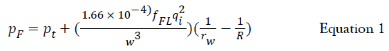
where pF is the bottom hole fracturing pressure in psi, pt in the fracture tip pressure in psi which is assumed to be equal to the minimum formation stress, fF is the Fanning friction factor, ρL is the fluid density in lbm/ft3, qi is the injection flow rate in bpm, rw is wellbore radius in ft, R is fracture radius in ft, and w is the average fracture width in inch. Because R >> rw, 1/R is negligible compared to 1/rw. Equation 1 implies that the fracturing pressure is essentially controlled by the fracture width w, not the fracture radius R.
The analytical solution presented by Geertsma and de Klerk [15] may be used for estimating the average fracture width form Equation 1 and The resultant equation 2 is
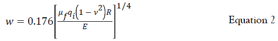
where μf denotes fluid viscosity in cp, ν is Poison’s ratio of rock, and E is Young’s modulus in psi.
Proppant selection model
A frac-pack well completion is a hybrid design that must incorporate formation sediment characteristics. The initial formation-sand control work in the industry focused on preventing sand production into the wellbore rather than on producing fluids through a gravel/sand/proppant pack. Coberly and Wagner [19] recommended that the gravel pack media should have particles with an average size 10 times that of the D10 of the formation particles. Numerous failures were noted, however, in the late 1930s, Hill [20] suggested that the ratio should be reduced from 10 to 8, which was done but with a similar lack of success. Later, investigators began to concentrate on the finer formation particles. Schwartz [21] developed a correlation based on the uniformity of the formation particles but for most conditions, the 40-weight percentile of gravel is chosen to be 6 times the 40-weight percentile of formation sand. The uniformity coefficient of gravel is required to be 1.5 or less, which gives the minimum gravel size of 0.615 times the 40- weight percentile of gravel and the maximum gravel size of 1.383 times the 40-weight percentile of gravel. Based on investigations of retention capability and the permeability of a gravel pack, Saucier [22] published his well-known recommendations that the gravel-pack media diameter be 5 to 6 times the formation particle median diameter. From this work, Saucier also concluded that rounded proppant is more desirable than angular proppant in gravel packs. His technique maximizes proppant conductivity by retaining the formation sand at the edge of the gravel pack, which essentially creates an enter-proof screen, rather than building a filter that captures formation fines within the proppant pack. Saucier’s results are logical when the geometry of a tight pack of spheres is considered. In a tight pack, particles smaller than 15% (1/6.5) of the pack grain diameter can invade the pack and reduce its effective permeability. Although using Saucier’s conservative sizing criteria allows efficient fines filtration, the highly impermeable layer that is often created at the formation/proppant interface can reduce well productivity. Saucier [22] gave no recommendation about gravel size distribution. If the uniformity coefficient of gravel is required to be 1.5 or less. Saucier’s [22] correlation gives the minimum gravel size of 0.667 times the 50- weight percentile of gravel and the maximum gravel size of 1.5 times the 50- weight percentile of gravel.
The more recent work by Jennings [14] has shown that using larger, synthetic proppants can improve well productivity and gravel-pack life, and still effectively control formation fines. In Jennings’ [14] work, several sand and ceramic proppants were tested with three different distributions of formation fines. The results show that Saucier’s criteria are conservative and suggest a mean proppant diameter at least 6 to 8 times the mean formation-particle diameter is more desirable. Testing showed that these criteria allow some invasion of fines, but that most of the fine material accumulates within the first few millimeters of the pack and is not allowed to flow through the column completely. This work is more in line with filtration theory, in which the majority of the proppant pack (Filter) is used to capture contaminants (fines), as opposed to merely creating a screen fine enough to preclude the entry of particles into the pack.
Proppant transport model
Fracturing fluid and its flow rate should be designed to possess certain properties favorable to transport proppant into the reservoir without early screenout. There exists a minimum fluid injection rate required to transport proppant to the fracture tip deep into the gas hydrate reservoir. The empirical model developed by Guo and Liu [23] for transporting drill cuttings in a horizontal wellbore can be used to predict the minimum fluid injection rate. The model computes the terminal slip velocity vsl of a particle in the carrying fluid using
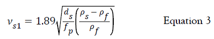
where vsl is solid particle slip velocity in ft/s, ds is equivalent particle diameter in inch, s is particle density in lbm/ft3, f is fluid density in lbm/ft3, and fp particle friction factor (dimensionless).
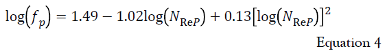
The particle friction factor fp is a function of the Reynolds number NRe and particle sphericity. The sphericity is defined as the surface area of a sphere containing the same volume as the particle divided by the surface area of the particle. Engineering charts are available for finding the values of the friction factor by Bourgoyne et al. [24]. For a conservative value of sphericity for proppant, 1.0, the following correlation is developed to replace the charts:
where the particle Reynolds number is defined as
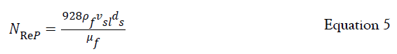
where μf is viscosity of fluid in cp.
Because the slip velocity is implicitly involved in Equations 3-5, the slip velocity can only be solved numerically. A computer program called Particle Slip Velocity.xls is developed in this study for easy calculations.
Based on the experience gained in horizontal well drilling engineering, the minimum fluid velocity required to mobilize solid particles in horizontal flow is about 1.5 vsl. Therefore the minimum fracturing fluid flow rate required to carry proppant deep into the fracture is expressed as
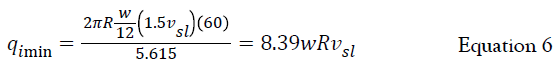
where qi min is the minimum required fracturing fluid flow rate in bpm.
Field Case Studies
The gas hydrate deposits in the Shenhu area, northern South China Sea, are under a seawater depth of about 3,870 ft [25]. The hydrate-bearing layer extends from 510 ft to 580 ft interval below the seafloor. The pressure gradient in the seawater is 0.465 psi/ft. The average reservoir pressure is estimated to be 0.465, 4415 or 2053 psia. Li et al. [12] reported the first production test on an offshore gas hydrate well in the Shenhu area in the South China Sea. The reservoir lithology is clayey silt, whereas, the mean effective porosity within interval "a" is 35%, the mean hydrate saturation is 34%, and the mean permeability is 2.9 mD. The mean effective porosity of interval "b" is 33%, the mean hydrate saturation is 31%, and the mean permeability is 1.5 mD. The mean effective porosity of interval "c" is 32%, the mean gas saturation is 7.8%, and the mean permeability is 7.4 mD. Table 1 provides a summary of reservoir parameters based on the analysis of gas hydrate samples from the site SH7 of GMGS-1 and GMGS-3 in the Shenhu area [26].
| Reservoir Parameters | Values |
|---|---|
| Reservoir thickness, ft | 70 |
| Reservoir pressure, psi | 2,053 |
| Reservoir temperature, °F | 57.7 |
| Matrix, md | 3.65 |
| Fracture permeability, md | 2,200 |
| Gas viscosity,cp | 0.018 |
| Propped fracture width, inch | 0.25 |
| Gas Z factor | 0.7 |
| Wellbore radius, ft | 0.328 |
| Wellbore pressure, psi | 1,000 |
| Proppant volume, ft° | 70 |
Table 1: Properties of gas hydrate reservoir and hydraulic fractures.
Proppant size requirement: For the offshore gas hydrate well in the Shenhu area in the South China Sea. Li et al. [12] reported that the median grain size of sediments was from 2.60 to 28.96 μm, and the average value is 8.49 μm. If Saucier’s [22] correlation is used, the median grain size of the proppant should be (8.49) (6) = 50.94 μm or 0.002 inch. Applying the uniformity coefficient of 1.5. Saucier’s [22] correlation gives the minimum proppant size of (0.667) (50.94) = 34.98 μm or 0.0013 inch and the maximum proppant size of (1.5) (50.94) = 76.41μm, or 0.003 inch. This range of grain size is equivalent to particle sizes from 333 mesh to 748 mesh, which is not available from commercial proppant products. Therefore, it would be economical to use screened natural sands in frac-packing operations.
Flow rate requirement: The flow rate of fracturing fluid should be designed high enough to carry the selected proppant/sand deep into the fracture tip without gravitational settling. Table 2 presents a summary of data used for calculations with the computer program Particle Slip Velocity.xls developed in this study using Equation 3-5. The programs gives vsl = 0.001 ft/s. Equation 6 yields bpm which is much lower than the practical values ranging from 20 bpm to 100 bpm. Therefore proppant/ sand transport is not a concern.
| Parameters | Values |
|---|---|
| Particle specific gravity (water=1) | 2.65 |
| Particle sphericity  (ball=1) | 1 |
| Fluid viscosity,cp | 20 |
| Fluid density, ppg | 13.1 |
| Fracture radius, ft | 510 |
| Fracture width,inch | 0.85 |
| Particle equivalent diameter, inch | 0.003 |
Table 2: Summary of parameter values for calculating the minimum flow rate.
Injection pressure requirement: Table 3 shows the data used for calculating the required fracturing fluid injection rate and fracturing pressure. The fracture-tip pressure is taken the minimum formation stress which is in the vertical direction for shallow deposits such as the marine gas hydrates. The minimum formation stress is calculated based on the pressure gradient of 0.456 psi/ft of water above the mud line and the overburden stress gradient below the mud line of about 1.0 psi/ft. Therefore, the minimum stress at the mid-zone depth 4,415 ft is about (0.465) (3,870) + (1.0) (545) or 2,345 psi. The friction factor is assumed a high value of 0.1 which is a conservative for friction pressure calculations.
| Parameters | Values |
|---|---|
| Young’s modulus of formation, psi | 1,470 |
| Posion ratio of formation | 0.2 |
| Wellbore radius, Ft | 0.328 |
| Viscosity of fracturing fluid, cp | 20 |
| Proppant concentration, v/v | 0.3 |
| Fracture tip pressure, psi | 2,345 |
| Density of fracturing fluid, 1bm/ft3 | 93 |
| Friction factor | 0.1 |
Table 3: Summary of parameter values for frac-packing calculations.
Using the data in Table 3, Equation 2 gives a fracture width of 0.83 inch during frac-packing. With a practical fracturing fluid injection rate of 72 bpm, Equation 1 predicts a bottom hole injection pressure of 2,378 psi which is only 334 psi above the reservoir pressure. Most pumps used in frac-packing operations can handle this pressure.
Discussion
The productivity of frac-packed hydrate gas wells is one of the most important issues in the feasibility analysis. Mathematical modeling of frac-packed hydrate wells is a very difficult task, considering hydrate decomposition mechanisms, thermodynamics, and phase changes inside hydrate reservoirs. Under given reservoir conditions and hydrate-decomposition scheme (depressurization, thermal stimulation, and/or chemical inhibition), fracture size (radius and width) is a major factor affecting well productivity. Well productivity is briefly analyzed in this paper with a simplified mathematical model. Model details will be presented in a separate paper due to its lengthy nature. Assuming single-phase gas flow under a reservoir pressure below the hydrate-decomposition pressure, the following analytical well productivity model was derived for quick assessment of well potential (derivation of the model is available upon request)
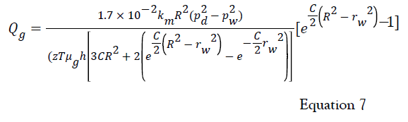
where is gas production rate in Mscf/d, is effective reservoir matrix permeability to gas flow in md, is the radius of fracture in ft, pd is hydrate-decomposition pressure in psia, is wellbore pressure in psia, is gas compressibility factor, and is formation temperature in °R, μg is gas viscosity in cp, is the thickness of gas hydrate reservoir in ft, rw is wellbore radius in ft, and
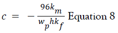
where wp is the propped fracture width in inch, and kf is fracture permeability in md. The decomposition pressure of methane gas hydrate at 57.7 °F is about 1,900 psia. Substituting the data in Table 1 and the fracture radius 510 ft into equation 8 gives an expected gas production rate of 16 MMscf/d which is considered as a commercial gas product.
Conclusion
A feasibility analysis of using frac-packing completion technique to produce natural gas from the offshore gas hydrate reservoir in the northern South China Sea was carried out in this work, focusing on requirements of proppant size, fluid injection rate, fracturing pressure, and well productivity. The following conclusions are drawn.
• The median grain size of sediments in the studied formation is from 2.60 to 28.96 μm with an average value of 8.49 μm. If Saucier’s correlation is used with a uniformity coefficient of 1.5, the required range of proppant size is between 333 mesh to 748 mesh (0.001 inch ~ 0.003 inch). Since the proppants in this size range are not commercially available, it would be economical to use screened natural sands as proppants in fracpacking operations.The minimum flow rate of fracturing fluid required to carry the 0.003 inch proppant/sand into the fracture tip at 510 ft without gravitational settling is 3.64 bpm, which is much lower than the practical values ranging from 20 bpm to 100 bpm. Therefore proppant/sand transport during frac-packing is not a concern.
• To create a horizontal fracture of 510 ft radius with a fracturing fluid injection rate of 72 bpm, the maximum bottom hole injection pressure is predicted to be 2,378 psi, which is only 334 psi above the reservoir pressure and can be handled by most pumps used in frac-packing operations.
• Well productivity analysis with a simplified mathematical model shows that a commercial gas production rate of 16 MMscf/day is achievable with a fracture radius of 510 ft. However, the model requires further validation.
Acknowledgments
This work was partially supported by the Bayu Talent Program of Chongqing City. This work was partially supported by Natural Science Foundation of China (NSFC, 51774063; Funder ID: 10.13039/501100001809), The National Key Science and Technology Project of China (Grant No. 2017ZX05009003-007; Funder ID: 10.13039/501100002855), The PetroChina Innovation Foundation (Grant No. 2016D-5007-0308; Funder ID: 10.13039/501100005154), The Science and Technology Innovation Special Project on Social Enterprise & People’s Livelihood Safeguard by Chongqing Science and Technology Commission of China (Grant No. cstc2017shmsA90004; Funder ID: 10.13039/501100002865), The Basic and Frontier Research Project by Chongqing Science and Technology Commission of China (Grant No. cstc2018jcyjAX0593; Funder ID: 10.13039/501100002865), and The Education Reform Project of Chongqing University of Science &Technology of China (Grant No. 201604; Funder ID: 10.13039/501100002338).
REFERENCES
- Wessells S, Stern L, Kirby S. USGS Gas Hydrates Lab: United States Geological Survey Multimedia Gallery Video, 2012.
- Folger P. CRS Report for Congress Prepared for Members and Committees of Congress, Congressional Research Service, Gas Hydrates: Resource and Hazard 2011.
- Moridis GJ, Reagan MT, Roswell, Boswell R, Collett TS, Zhang K. Preliminary evaluation of the production potential and recently discovered hydrate deposits in the Gulf of Mexico. Paper OTC 21049 presented at the 2010 Offshore Technology Conference held in Houston, Texas, USA, 2010.
- Gaddipati M, Anderson BJ. 3D Reservoir Modeling of Depressurization-Induced Gas Production from Gas Hydrate Reservoirs at the Walker Ridge Site, Northern Gulf of Mexico. Paper OTC 23582 presented at the Offshore Technology Conference held in Houston, Texas, USA, 2012.
- Koji Y, Terao Y, Fujii T, Ikawa T, Seki M, Kanno T, et al. Operational overview of the first offshore production test of methane hydrates in the Eastern Nankai Trough." In Offshore Technology Conference. Offshore Technology Conference, 2014.
- Yamamoto K. Overview and introduction: pressure core-sampling and analysis in the 2012–2013 MH21 offshore test of gas production from methane hydrate in the eastern Nankai Trough. Mar Petrol Geol. 2015;14:296-309.
- Guo X, Liu F. China announced combustible ice test success in the Shenhu area, South China Sea. 2017:5-18.
- Zhou S, Li Q, Wei C, Zhou J, Pang W, Yufa H, et al. The world’s first successful implementation of solid fluidization well testing and production for non-diagenetic natural gas hydrate buried in shallow layer in deep water. In Proceedings of the Offshore Technology Conference, Houston, Texas, USA. 2018;30:2784-2794.
- Wu SG, Wang JL. On China's successful gas production test from offshore gas hydrate reservoirs. Chin Sci Bull. 2018;63:2-8.
- Zhou S, Zhao J, Li Q, Chen W, Zhou J, Wei N, et al. Optimal design of the engineering parameters for the first global trial production of offshore natural gas hydrates through solid fluidization. Nat Gas Ind B. 2018;5:118-131.
- Jin Y, Konno Y, Nagao J. Growth of methane clathrate hydrates in porous media. Energy & fuels.2012;26:2242-2247
- Li J, Ye JL, Qin XW, Qiu HJ, Wu NY, Lu C, et al. The first offshore natural gas hydrate production test in the South China Sea, China Geology 2018;1: 5-16.
- Ghalambor A, Ali SA, Norman WD. Frac Packing Handbook, Society of Petroleum Engineers, Richardson, Texas, USA, 2009.
- Jennings AR. Laboratory studies of fines movement in gravel packs, SPE Drilling & Completion. 1997;12:275-281.
- Geertsma J, De Klerk F. A rapid method of predicting with and extent of hydraulic induced fractures. J Pet Technol. 1969;21:1571-1581.
- Perkins TK, Kern LR. Width of hydraulic fracture. J Pet Technol. 1961;13:937-949.
- Sneddon IN. The distribution of stress in the neighborhood of a crack in an elastic solid. Proc Royal Soc. London, UK. 1946;187:229-260.
- Sneddon IN, Elliott AA. The opening of a Griffith crack under internal pressure. Quart Appl Math. IV 1946; 262-267.
- Coberly CJ, Wagner EM. Some considerations in the selection and installation of gravel packs for oil wells, Trans. Petroleum Technology 1938;127:1-20.
- Hill KE. Factors affecting the use of gravel in oil wells. Oil Weekly 1941;13-20.
- Schwartz DH. Successful sand control design for high-rate oil and water wells. J Pet Tec. 1969;21:193-1198.
- Saucier RJ. Considerations in gravel pack design. J Pet Tec. 1974;26:205-212.
- Guo B, Liu G. Applied drilling circulation systems, Gulf Professional Publishing, 2011.
- Bourgoyne AT, Millheim KK, Chenevert ME, Young FS. Applied Drilling Engineering, SPE Textbook Series, Dallas, Texas, USA, 1986.
- Su M, Yang R, Wu NY. Structural characteristics in the Shenhu Area, northern continental slope of South China Sea, and their influence on gas hydrate. Acta Geol Sin. 2014;88:318-326.
- Dorf RC. The Engineering Handbook, CRC Press, Baca Baton, USA, 1995:1026-1027.
Citation: Hou X, Guo B, Ekhator E (2020) Technical Feasibility of Using Frac-Packed Wells for Producing Natural Gas from Offshore Gas Hydrate Reservoirs. J Pet Environ Biotechnol. 10:400. doi: 10.35248/2157-7463.20.11.400
Copyright: © 2020 Ekhator E, et al. This is an open-access article distributed under the terms of the Creative Commons Attribution License, which permits unrestricted use, distribution, and reproduction in any medium, provided the original author and source are credited.