


Indexed In
- Open J Gate
- Genamics JournalSeek
- JournalTOCs
- China National Knowledge Infrastructure (CNKI)
- Electronic Journals Library
- RefSeek
- Hamdard University
- EBSCO A-Z
- OCLC- WorldCat
- SWB online catalog
- Virtual Library of Biology (vifabio)
- Publons
- MIAR
- Euro Pub
- Google Scholar
Useful Links
Share This Page
Journal Flyer

Open Access Journals
- Agri and Aquaculture
- Biochemistry
- Bioinformatics & Systems Biology
- Business & Management
- Chemistry
- Clinical Sciences
- Engineering
- Food & Nutrition
- General Science
- Genetics & Molecular Biology
- Immunology & Microbiology
- Medical Sciences
- Neuroscience & Psychology
- Nursing & Health Care
- Pharmaceutical Sciences
Review - (2019) Volume 10, Issue 5
Sensitivity Analysis of the Influence of Fracturing Spacing in the Construction of Complex Fractures Network for Exploration and Production of Shale Gas/Shale Oil
Fernando Bastos Fernandes1,2,3*, Wellington Campos1, Arthur Martins Barbosa Braga1, Celeste Yara dos Santos Siqueira2, Marcelo Alves Otaviano Botelho3, Fernando Henrique Guimarães Rezende2, Antônio Cláudio Soares1, Marcos Antônio Rosolen4 and Almir Carvalho de Souza Filho22Federal University of Rio de Janeiro (UFRJ), RJ, 21941-901, Brazil
3Petróleo Brasileiro S.A. (Petrobras), Brazil
4State University of Campinas (UNICAMP), Brazil
Received: 26-Aug-2019 Published: 25-Oct-2019, DOI: 10.35248/2157-7463.19.10.397
Abstract
Shales reservoirs have a high degree of anisotropy due to the presence of natural fractures (NFs) and also the orientation of beddings. Thus, hydraulically induced fractures (HFs) interact with natural fractures and generate a network of fractures with complex geometry. The existence of NFs modifies the stress field in the shale and directly influences the geomechanical behaviour of the HFs during the fracturing operation, generating branches in the dominant fracture and contributing to the complex network of fractures. The construction of a network of fractures increases significantly the conductivity of the formation, as it connects previously isolated fractures and pores, thus increasing the productivity index of the wells and providing greater economic viability in the shale gas/oil reservoir designs. This work presents a sensitivity analysis of the influence of fracturing spacing in the construction of the network of complex fractures generated in shales, aiming to understand how this parameter modifies the volume of stimulated reservoir (SRV) and the distribution of propant in the network of fractures, in order to avoid problems in this step of the design and thus, maintain the economic viability of the network. The literature review includes the main published works on this subject and the unconventional fracture models (UFM) used to model the network of complex fractures. Sensitivity analysis will be performed using the MShale software, which uses a stochastic model of the discrete fracture network (DFN) method and numerically solves the equilibrium equations and pore elasticity for shales in terms of effective stresses, in addition to mass conservation equations, linear momentum and energy with viscous dissipation for stokes creeping flow. For the analysis, the other parameters that influence the construction of the network will be kept constant and only the spacing between fracturing will have variation.
Keywords
Shales reservoirs; Organic matter; Source rocks; Conventional reservoirs; Unconventional reservoirs
Abbreviations
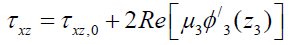
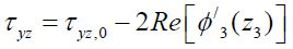
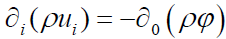
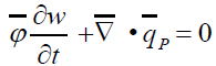
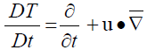
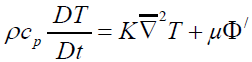
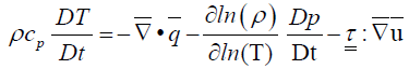
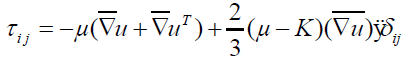
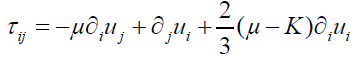
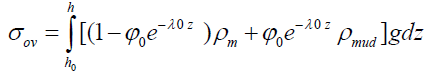
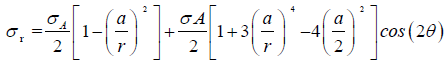
k: Permeability; g: Gravity’s aceleration; φ: Porosity; ν’: Knematic viscosity; Kcc: Kozeny-Carman’s coefficient; D: Grain’s diameter; pfrac: Pressure of breakdown; σh: Minimum horizontal stress; σH : Maximum horizontal stress; T0: Tensile’s strength; pp: Pore pressure; δp(t): Drop of pressure inside the NFs; pn,h(t): Drop of pressure among NFs and HFs; kn: NF’s permeability; t: Time; φn: NF’s porosity; μ: Dynamic viscosity; Cr: Compressive resistent coeficient; Ln: Lengh of NF; Rn: Net pressure’s coefficient; pi: Pumping pressures; σij: Cauchy’s stress tensor; ∇: Nabla operator; σii: Normal stress’s tensor; τij: Shear stress’s tensor; < σ >: Volume averaged stress; εii: Normal strain’s components; Γij: Shear strain’s components; E: Young’s moduli; G: Shear moduli or 1st Lam´e’s parameter; λ: 2nd Lame’s parameter; ν: Poisson’s coeficient; λ0: Decay’s parameter; σov: Overbourden Stress; σθ: Azimutal stress; σr: Radial stress; σA: Uniform load apllied on the rock; a: Radius of the wellbore; ρmud: Density of the fluid inside the pores of the rock; ρm: Density of the matrix; z: Depth; δij: Kronecker’s Delta tensor; Cijkl: Hardness matrix; εkl: Strain’s matrix; [A]: Elasticity’s tensor for in situ stresses coordinates; ψ : Elasticity’s tensor in beddings coordinates; ψ w: Elasticity’s tensor in well coordinates; σi/j: Effective stresses; α: Poroelasticy’s or Biot’s coeficient; pw: Well’s pressure; σj, 0 and τjl, 0, (j, l=x, y, z): Are the components of normal and shear stresses away from the well; σj and τjl, (j, l=x, y, z): Are the components of normal and shear stresses around the well; u: vector field of speed; qi(x, t): Pumping rate; uL: Leak-off speed; η: Difusivity’s coeficient; qS: Slurry rate; qP: Propant rate; < φ > : Normalized averaged porosity; T: Temperature; cp: Specific heat to constant pressure; K: Thermal’s condutivity constant; φ’: Viscous dissipation function; q: Vector heat’s flow.
Introduction
The generation of oil occurs in sedimentary basins such as lakes, oceans, rivers and marshes, where sedimentary rocks with large amounts of fine grains, clay and silt are deposited over millions of years and carrying a certain volume of organic matter accumulated in the interior of their pores [1], Such rocks are called source rocks [2]. After the maturation of the organic matter present in the source rock, a natural fracture occurs in the same one, due to the conditions of high pressure and temperature, generating the primary migration of the hydrocarbon for its later imprisonment in a rock with high permo-porous properties, denominated rock reservoir [3]. The next step of the conventional petroleum system generating mechanism is to surround the reservoir by means of traps and a sealant rock, i.e. with low permeability, e.g. evaporite (salt) or shale itself, thereby preventing the hydrocarbon be drained to other layers [3].
The shale gas /shale oil system is different from the conventional reservoirs (CR) mentioned above, since shales are part of a group known in the literature as unconventional reservoirs (NCR), because the primary migration has not yet occurred and also, because the shales have low permo-porous properties. Thus, the drilling operation is done straight on the source rock, so the shales are classified as source-reservoir rocks (SRR) [4]. The structure of the shales is basically formed by clastic or detrital rocks. Its formation is by means of transport by water or air. Such rocks are usually composed of silica, combined with other common minerals such as feldspar and clay minerals, e.g. quartz, limestone and feldspar, which have low granulometry, making it difficult to explore shale gas /shale oil without use stimulation techniques. Another characteristic of the shales is to possess high total organic content, TOC [5].
In the last decades, the advances in directional/horizontal drilling technologies, through rotary steerable systems (RSS), which allowed for better control of the well trajectory, and also in hydraulic fracture stimulation techniques (Figure 1), allowed economical exploration and shale gas/shale oil reserves in the world [6].

Figure 1: Hydraulic fracturing operation by constructing a horizontal well in a shale gas reservoir.
The main challenge of petroleum engineering for the exploration and production of shale gas/oil reservoirs is that their geomechanical properties are very different from conventional reservoirs. A big volume of natural gas is still confined to the source rock as the shale and, therefore, requires a stimulation technique so that its extraction is economically feasible [7]. In general, the main characteristics of shales are:
• Large variations in mineralogy [8];
• High anisotropy and heterogeneity, due to the laminations of the depositional process, [9];
• Porosity between 2 % and 15 %, [10];
• Presence of high volume of organic matter [11];
• High degree of brittleness [12];
• Presence of natural fractures [13];
• Permeability between nanodarcy and microdarcy [3].
The main objective of this work is to understand how the fracturing spacings influence the support of the network of complex fractures and SRV in the construction of the network of complex fractures, (Figure 2) in order to optimize the flow of shale gas/shale oil to the well [14].

Figure 2: Effect of the spacing between the fractures in the SRV of a shale gas/oil reservoir.
Problem statement
The stimulation of a certain formation by means of the hydraulic fracturing technique consists in the pumping of a high pressure fracture fluid and controlled flow in a producing zone that has low permo-porous properties, in order to exceed its limit poroelastic and to generate artificial fractures which aim to increase the productivity index of the well by increasing the conductivity and permeability of the payzone. Usually it is the zone where the oil reservoir is located. In shale exploits, the pay zone is the range of the shale itself being traversed. In conventional reservoirs, the HF propagates in a two-wing shape, however, in shale gas/shale oil reservoirs, due to some geomechanical, hydraulic and design parameters, the activation of natural fractures occurs through the HFs, building a network of complex fractures [15,16].
Thus, the hydraulic fracturing operation has the purpose of:
• Connecting isolated pores and existing natural fractures and with this, build a network of complex fractures;
• Exceeding the radius of damage caused by the skin effect during the drilling operations, due to the invasion of gravels in the formation pores and also the projectiles in the cannon phase.
According to Gandossi [17], the fracturing fluid consists of: Base Fluid + Additives + Sustaining Agent (AS). The construction of a network of fractures increases SRV and with this also occurs the increase of shale gas production, [14]. After the fracture network is built up, the fracture fluid is replaced by a fluid with greater transport properties of AS for its lodging inside the network and to provide support for it [18].
The main parameters that influence the network behavior of complex fractures in shales are:
• Fracturability [9];
• Number of existing natural fractures [19];
• Spacing between fractures [19];
• Shale’s degree of brittleness [22];
• HF intersection angle with NFs [20,21];
• Flow speed and pumping pressure of the fracturing fluid [23];
• Dynamic viscosity of the fracturing fluid [22].
Normally, the shales have several natural fractures present in the rocky matrix and a high degree of brittleness. In this way, the hydraulic fracturing design aims to build a network of hydraulic fractures connected to the pre-existing natural fractures, generating multiple channels within the formation, to optimize the flow of shale gas to the well through a large increase [24,25].
In a hydraulic fracturing design in shales, the following parameters should be considered:
• Type of fracturing fluid, [8];
• Pressure and pumping flow of the fracturing fluid, because the higher the injection flow, the lower the pressure required in the pumping of the fracture fluid to overcome the resistance limit of the rock and generate the fracture [23];
• Between Fractures;
• Dynamic viscosity of the fracturing fluid, because viscosity variations generate different behavior of the network of complex fractures [26];
• Fracture volume, to estimate the volume of propant to be used;
• Breakdown pressure [27];
• Permeability and anisotropy of SRR;
• Existence of natural fractures in SRR [28];
• Containment stresses [23];
• Controlling the orientation of the fracture, as the propagation of the same in a disordered way can reach adjacent layers, water tables and neighboring wells [29].
In addition to the parameters mentioned above, for a hydraulic fracturing operation in shales to be successful, it is necessary that the rock has great fracturability property, i.e., the capacity of the shale to propagate the dominant fracture with several secondary fractures connected to it [30], in order to obtain the highest reservoir volume value possible.
High fracturability is associated with friable shale regions, with high modulus of elasticity and low Poisson ratio. In these conditions a wide and stable fracture network is created [31,32].
Literature Review
The development of numerical methods that simulate the behavior of the network of complex fractures in shale gas/shale oil reservoirs has been a huge challenge among engineers of stimulation and researchers of the petroleum industry in the last decade. As previously mentioned, the traditional models used in conventional reservoirs do not adequately reproduce the behavior of the fracture network in shales [33]. Thus, unconventional models for the adequate modeling of the problem take into account the effects of very low permeability, high heterogeneity and also anisotropy of the formations.
Main published studies about the subject
Singh [34] studied a rock intercepted by a single set of uniformly distributed joints footnote and found the equivalent modulus of elasticity for the whole system.
Meyer [35] developed a solution that takes into account the effects of natural convection heat transfer between the fracture fluid and the rock and by means of the Nusselt number, obtained a coefficient to consider the thermal effect during the operation the hydraulic fracturing.
Cho et al. [36] presented the equivalent constitutive equations that describe the mechanical behavior of the rock and the fluid in its interior and with several orientations of the joints. The model assumes that the behavior of the rock is elastic-linear and with isotropic permeability of the intact rock. The theory obtained can be used to take into account the effect of anisotropy due to the orientation of the joints. Huang et al. [37] proposed a model based on the stress-strain relationship that treats the intact rock mass (with very low permeability) and the fractured mass (with high permeability) separately. Thus, the equations of the modulus of elasticity for the rock with 3 joints are obtained as a function of the fracture properties also of the intact rocks.
Fisher et al. [38] carried out hydraulic fracture diagnosis design in Barnett’s naturally fractured shales and showed that the fracture half-length was a function of the volume of fluid injected in the time interval during which this half-length stopped propagating, after a significant amount of fluid volume is injected into the formation. The length and width of the SRV were observed using micro-seismic monitoring.
Maxwell et al. [39] observed the micro-seismic events monitored during hydraulic fracturing in a naturally fractured shale also of Barnett and found that, from micro-seismic observations that HF occasionally grew at an oblique angle with the direction of fracture assumed. The results also showed that hydraulic fractures grew at an oblique angle because they crossed the natural network of fractures.
Rutqvist and Stephansson [40] have investigated several equivalent continuous models for the fractured medium. One of the simplest approximations is based on a set of three fractures orthogonal to each other in a cube of the porous medium, in which the equations of continuity and elasticity can be solved in an easier way.
UFM models
Roussel and Sharma [41] presented an unconventional two-dimensional numerical model and demonstrated that a transverse fracture to a horizontal well can be diverted due to the redistribution of in situ tensions generated by the existence of natural fractures. Thus, a poroelastic model to simulate the stress interference between fractures in horizontal wells was formulated. In these calculations, an HF is represented by the PKN geometry [42,43].
The model was constructed using FLAC-2D (Fast Lagrangian Analysis of Continua) and is based on the explicit finite difference method in 2-D, where each derivative in the set of equations that model the phenomenon is replaced directly by an expression algebra written in terms of field variables e.g. stress or displacement at discrete points in space.
Meyer and Bazan [35] purposed one of the most commonly used unconventional models for fracture network behavior in shale gas/oil reservoirs: The MShale, which consists of a discrete fracture network (DFN) simulator in naturally fractured formations, e.g. shales and coal bed methane (CBM). The software uses stochastic modeling based on some functions of probability distributions and is used to verify several existing numerical models since it can be used as a diagnostic tool to compare the numerical results of the DFN model with micro seismic data. Thus, through Mshale, the propagation of the network of complex fractures in several planes in shales can be simulated with the specification of the grid.
Belytschko and Black [44] numerically modeled fracture propagation using the Extended Finite Element Method (XFEM), where space-solution enrichment of the problem with discontinuous functions was used to represent the surface and asymptotic functions for the representation of the other regions of the fracture. XFEM has the advantage of avoiding the problem of remeshing and can find singularities of the field of tensions using the original system of the mesh. The disadvantage of the method is that additional degrees of freedom modify the original structure of the matrix and the need for longer processing time due to the need to integrate numerically each step of the simulation. XFEM is suitable for problems involving the propagation of fractures in heterogeneous media such as shale [45].
Parameters that influence the construction of the network of complex fractures in shale gas/shale oil reservoirs
Net Pressure: Olson and Dahi-Taleghani [46] showed that the net pressure directly influences the construction of the network of complex fractures. Normally the analysis of the influence of the liquid pressure on the interaction between hydraulic fractures and natural fractures is carried out by means of the net pressure coefficient, expressed by:
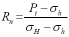 (1)
(1)
Dynamic viscosity of the fracturing fluid
The dynamic viscosity of the fracture fluid in shales has a direct influence on the construction of the fracture network, because as the fluid viscosity increases, the extent of the fracture network is significantly reduced [47].
Experimentally, it has been found that a high viscosity fracturing fluid contributes to the generation of the planar fracture pattern and a low viscosity fluid, such as slickwater fracturing, generates the network pattern of complex fractures [47].
Pumping rate
Gomaa et al. [23] investigated the influence of the fracture fluid pumping rate during the slickwater fracturing operation on shales and realized that increasing the flow gives a reduction in the fracturing pressure of the sample.
Distribution and orientation of natural fractures
According to previous considerations, during the hydraulic fracturing process in shale gas/shale oil reservoirs, natural fractures are activated in order to allow the gas trapped in the shale pores to flow to the well and optimize the stimulation operation [48]. Field tests have shown that any HF in a naturally fractured medium is influenced by the approach angles of the NFs and generates a network of complex fractures. Guo et al. [49] verified that the amount and pattern of fracture orientation directly influenced the shape of the network of complex fractures.
Beddings’s direction: Beddings are planar sedimentary structures generated by the deposition of lithological layers overlapping each other. In rocks such as shale, which have different types of granulometry and mineralogical composition, the visualization of beddings is more evident [50].
Gomaa et al., [23] have verified experimentally that the direction in which Beddings are accommodated directly influences fracturing pressure and pumping time.
Stress shadowing effect: Ren et al. [8] found experimentally, through a triaxial test in a naturally fractured medium that the HF propagates along the NF to low values of horizontal stress difference and crosses the natural fractures to high values of tension difference horizontal, generating modification in the network behavior of complex fractures. Thus, the presence of a natural fracture close to the hydraulic fracture alters the stress field in the domain considered [51]. The presence of natural fractures also alters the geometry of HF and how it propagates. This effect is called stress shadowing and can change the trajectory of the hydraulic fracture. Thus, as mentioned previously, the spacing between fractures also influences the behavior of the HF being generated.
Interaction among HF-NF: Ren et al. [52] realized that different settings of fracturing influenced at the construction of the complex fractures network, and purposed 2 kinds of fracturing sequences: segmented hydraulic fracturing and multi-cluster hydraulic fracturing.
Mineralogical composition, modulus of elasticity and Poisson coefficient
The shale’s brittleness is directly correlated with its mineralogy, modulus of elasticity and Poisson’s coefficient. As the concentration of feldspar, quartz and calcite containing silicon or calcium increases, clay concentration decreases and increases the brittleness of the rock, i.e, it reduces its capacity to undergo deformation under the action of tensile stress in the elastic regime [53,54].
Zou et al. [55] realized that for the economically viable exploration of shale gas/ oil and the construction of complex fracture networks, the mineral concentration in the rock should be between 46% and 60%. In order to characterize the brittleness of shales, it is necessary to combine the modulus of elasticity and the Poisson coefficient.
Equations for a hydraulic fracturing design in shales
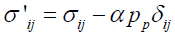
Mechanic formulation: The equilibrium’s equation in the tensor form for the problem of fracture propagation in an isotropic, elastic- linear porous medium with small deformations is given by:
 (2)
(2)
 (3)
(3)
Where:
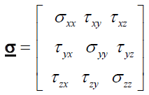
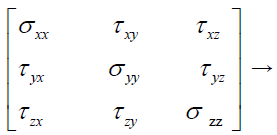
is called the “Cauchy stresses’s tensor”.
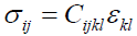
According to (Sayers, 2005), for an anisotropic formation like the shale, the modified Hooke’s law is given by:
 (4)
(4)
Making the change of the coordinate system (x, y, z) → (x1, x2, x3), the Cauchy’s stresses tensor becomes:
 (5)
(5)
Realizing the matrix product, we have:
 (6)
(6)
 (7)
(7)
 (8)
(8)
 (9)
(9)
 (10)
(10)
 (11)
(11)
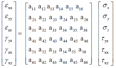
By generalized Hooke’s law, the constitutive equation for strain as a function of stress for an anisotropic formation is
 (12)
(12)
In the matrix form, one has:
{ε } = [A]{σ } (13)
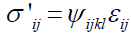
The constitutive equations of poro-elasticity for anisotropic formations
According to Zhu et al. [56], the constitutive equations for an anisotropic poroelastic model, in terms of effective stresses, are:
 (14)
(14)
 (15)
(15)
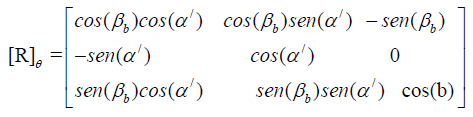
The rotation matrix [R]θ that transforms the stress coordinates system in situ to the well coordinate system is expressed by:
 (16)
(16)
 (17)
(17)
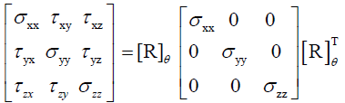
The stresses’s state in well coordinates is given by:
The tensor of elasticity ψ, in coordinates of the bedding plane, is:
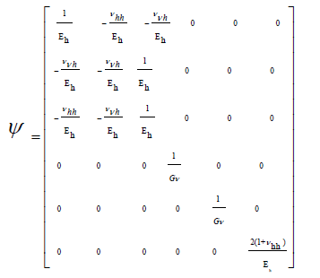 (18)
(18)
For the mechanical stability analysis in sloped wells, the tensile tensor above must be modified for well coordinates.
Thus, the modified elasticity tensor ψw is given by:
ψw = qψ q (19)
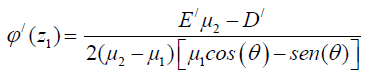
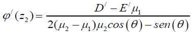
Lekhnitskii, Amadei, Aadnøy and Ong [57-60], have proposed exact solutions to the mechanical problem around sloping wells in shales taking into account the effects of anisotropy. The solutions are given in terms of complex variable functions according to the expressions:
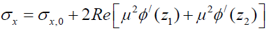 (20)
(20)
 (21)
(21)
 (22)
(22)
 (23)
(23)
 (24)
(24)
 (25)
(25)
Where:
 (26)
(26)
 (27)
(27)
 (28)
(28)
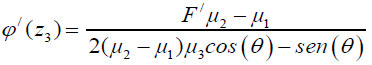
The functions of complex variables D’, E’ and F’ are expressed by:
 (29)
(29)
 (30)
(30)
 (31)
(31)
Hydraulic formulation for porous media
Mass conservation: The mass conservation equation, or continuity equation, shows that ”the sum of the rate of mass change within the control volume and the convective liquid mass flow on the control surface must be zero.”
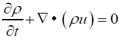 (32)
(32)
In a porous media with compressible fluid, the tensor form of the continuity equation is:
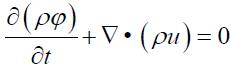 (33)
(33)
In the differential form, one has:
 (34)
(34)
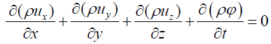
And finally, in index notation:
 (35)
(35)
The mass balance in the pumping of the fracture fluid for the formation is:
 (36)
(36)
 (37)
(37)
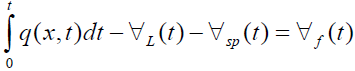
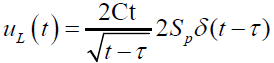
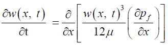
Nordgren [43] considered the leak-off effect in the Perkins and Kern model, arriving at the following integral- partial differential equation for the mass balance in the injection phase:
 (38)
(38)
In terms of the aperture width w(x, t) e of the fracture height hf we have the following partial differential equation:
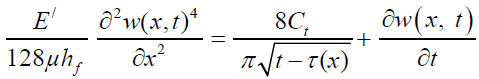 (39)
(39)
Entering variable change:
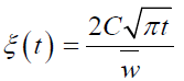 (40)
(40)
With the global leak-off coefficient Ct, expressed by:
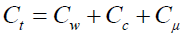 (41)
(41)
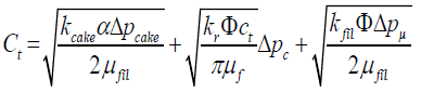 (42)
(42)
Or:
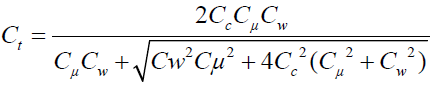 (43)
(43)
Finally, the area of space is:
 (44)
(44)
The momentum’s transport’s equation
The linear momentum conservation equation in the material form, i.e., following the movement of the fluid within the fracture and in terms of stress, is given by:
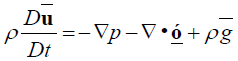 (45)
(45)
In terms of speed and convective heat transfer:
 (46)
(46)
From the Reynolds’s lubrication’s theory, for the Hagen- Poiseuille flow, in terms of the aperture, we have the following partial differential equation for the flow of the fracturing fluid inside the fracture:
 (47)
(47)
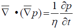
The hydraulic diffusivity equation
The equation of mathematically modeling the behavior of pressure as a function of distance and time during the single-phase flow of Newtonian fluids within the pores of a rock is termed the hydraulic diffusivity equation obtained by combining the continuity equation, Darcy’s law and equations of fluid and rock matrix compressibility and is expressed in the tensor form, as ”the divergence of the pressure gradient”:
 (48)
(48)
 (49)
(49)
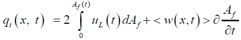
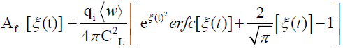
The propant’s transport equations
For the mathematical modeling of propant transport, the flow consists of two equations: One equation models the liquid phase and another the solid phase (Figures 3a-3c).

Figure 3a: Concentration of propant and SRV for A-S=10 m; B- S=11 m; C- S=12 m.

Figure 3b: Concentration of propant and SRV for D-S=15 m; E- S=16 m; F- S=18 m.

Figure 3c: Concentration of propant and SRV for G-S=20 m; H- S=25 m.
In this way, we have:
 (50)
(50)
 (51)
(51)
Thermal formulation (The energy equation)
During the flow of the fracture fluid inside the rock pores and later, in the network of complex fractures, convection and conduction heat transfer occurs. The contact of the fluid with the surface of the rock, turns a part of the mechanical energy of the flow into heat due to the viscous dissipation. The equation that mathematically models this where
 (52)
(52)
phenomena is the energy equation expressed in the material form and in temperature terms by:
 (53)
(53)
And, in heat flow terms by:
 (54)
(54)
In tensor notation:
 (55)
(55)
Or, in index notation:
 (56)
(56)
Numerical simulation
Petrobras full version of MShale was not available to simulate the whole real subjects about their stimulated wells due information security, thus it could not be used. So, for numerical simulation, the following assumptions for the mechanical, hydraulic, thermal and proppant transport problems were considered:
• Linear, isotropic and homogeneous elastic porous medium; Compressibility of the negligible porous medium;
• Spurt Loss inconsiderate;
• Fracturing fluid with Newtonian, single-phase and incompressible behavior;
• Proposed transport fluid with non-Newtonian behavior with power law model;
• Leak-off effect considered by the Carter model;
• Non-isothermal flow;
• Incompressible flow, i.e., ∇ • u= 0;
• Flow without active body force;
• Azimuth symmetry, i.e., uθ = 0;
• Darcian flow in the porous medium;
• Non-slip condition on the walls of the fracture, i.e., u¯(0) = 0
• Viscous dissipation Φ/;
• Creeping flow extremely laminar flow during the pumping of the fracture fluid in intact rock and deformed rock;
• Hagen-Pouseuille flow inside the fracture modeled by the Reynolds lubrication theory.
Discussion
This work showed that for the stimulation of a given payzone of shale gas/shale oil by means of the construction of a complex network of fractures, several geomechanical, hydraulic and geometric parameters are directly correlated (Table 1). In this way it was verified that:
| Design parameters | ||||
| Depth (TVD) | Simulation Time for each spacing | Number of fracture stages | Fracture spacing | Initial pumping rate of the slurry |
| 2502 m | 120 min and | 23 | 10 m, 11 m, 12 m, | 45 bpm |
| 150 min | 15 m, 16 m, 18 m, | |||
| 20 m and 25 m | ||||
| Fluid parameters | ||||
| Type of fracturing fluid | Average Reynolds Number | Medium Fluid Consistency Index | Medium Transport Fluid Power Index | Type of AS |
| Slickwater with | 205 | 0.5 lbf.sn/ft | 0.8 | Proppant |
| friction reducer | ||||
| Rock parameters | ||||
| Shale Elastic Modulus | Poisson coefficient | Overbourden stress gradient | Payzone | Average Permeability |
| 5MPSI | 0.25 | 0.85 PSI/ft | 210 m | 0.2 nD |
Table 1: Parameters construction of complex fractures in shales.
• The higher the net pressure coefficient, the higher the SRV;
• In fragile shale gas/shale oil reservoirs, with low values of dynamic viscosity of the fracturing fluid, the construction of the network of complex fractures occurs with greater ease;
• As the pumping flow of the fracturing fluid increases, the pressure required to fracture the formation decreases, but in the field, high pressure values are applied to ensure that the formation is fractured. With this, there is a need to hire more trucks equipped with high pressure pumps, increasing the CAPEX of the project;
• The operational sequence and intervals between fractures influence in the construction of the network and increase of the SRV, since neighboring fractures disturb the field of tension of the formation, generating the stress effect shadowing, causing a curvature in the fractures located in the ends of the spacing between fractures and reducing the size of the fracture located at its midpoint due to the reorientation of the stress field in the vicinity of the generated fractures and reducing the permeability of this stimulated region. This reorientation of the tensile field also provides a change in the propagation direction of the HFs and negatively influences the construction of the network of complex fractures;
• The existence of natural fractures and their orientation angles directly influence the construction of the network of complex fractures, since they also alter the field of formation tensions, so that the larger the number of natural fractures and the more disordered its distribution, the greater the extension of the fracture network. For the approximation angle of 90, the HF crosses the NF as if it did not exist. Thus, by means of microsysmica, one can look for zones with great quantity of natural fractures and with orientations favorable to the construction of the complex network to realize the hydraulic fracturing and to optimize the project of stimulation;
• In the fracture settling phase of the fracture, the dynamic viscosity of the fracture fluid must be higher than in the fracture network construction phase, since low dynamic viscosity fracturing fluids, e.g. slickwater, have low transport property proponent;
• It was verified that the more fragile the shale, the network of complex fractures is constructed more easily, since the formation undergoes breakout in several directions, connecting more pores and natural fractures;
• experimentally verified that parallel beddings provide shale breakout at shorter intervals of time and pressure than perpendicular beddings;
• By means of the numerical simulation, for the shale gas reservoir in question, it was observed that for spacings between fractures of 10 m, 11 m, 12 m, 15 m, 16 m and 18 m, there was an increase in SRV with uniform distribution of the propant in the fractures and with this, the network remained mechanically sustained;
• For larger spacing (between 20 m and 25 m), SRV continues to increase, but the network of fractures is not mechanically supported due to the disordered distribution of the propant, so the hydraulic fracturing design with spacing within this range is not economically viable.
 (57)
(57)
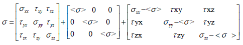
Total Stresses’s state hydrostatic state diverting stresses (Distortion)
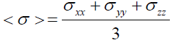
Where < σ > is the volume averaged stress, given by:
 (58)
(58)
By the generalized Hooke’s law for elastic, isotropic, homogeneous and symmetric shear stress components, i.e., τij = τji, we have that the stress components in Cartesian coordinates are expressed by:
σx = (λ + 2G)εx + λ(εy + εz) (59)
σy = (λ + 2G)εy + λ(εx + εz) (60)
σz = (λ + 2G)εz + λ(εx + εy) (61)
τxy = G.Γxy (62)
τxz = G.Γxz (63)
τxz = G.Γxz (64)
τyz = G.Γyz (65)
 (66)
(66)
 (67)
(67)
 (68)
(68)
 (69)
(69)
 (70)
(70)
 (71)
(71)
In Index Notation:
 (72)
(72)
Where λ and G are the Lam´e’s parameters, given by:
 (73)
(73)
The profile of stresses around boreholes, in cylindrical coordinates, is given by Kirsch’s equations:
 (74)
(74)
 (75)
(75)
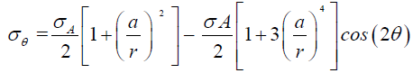 (76)
(76)
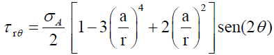 (77)
(77)
Acknowledgments
I thank God, my dad Antonio Carlos Fernandes (In Memoriam), my mom Rosa Maria Bastos Fernandes, my dear wife Danielle Salles Sampaio and our daughter Meg and to Pontifical Catholic University of Rio de Janeiro (PUC-Rio) and PETROBRAS.
REFERENCES
- Huc AY. Paleogeography, paleoclimate, and source rocks, Editor, Institute Francais Du Petrole. AAPG Studies in Geology. 1995;40:347.
- Klemme HD, Ulmishek GF. Effective petroleum source rocks of the world: Stratigraphic distribution and controlling depositional factor, AAPG Bulletin. 1991;12:1801-1851.
- Halliburton. Digital asset. 2012; Houston, Texas.
- Wang W, Lee T, Reed MA. Mechanism of electron conduction in self-assembled alkanethiol monolayer devices. Phys Rev. 2003;68:035416
- Orangi A, Nagarajan NR, Honarpour MM, Rosenzweig JJ. Unconventional shale oil and gas-condensate reservoir production, impact of rock, fluid, and hydraulic fractures. Soc Pet Eng. 2011;SPE-140536-MS.
- Gao J, You F. Design and optimization of shale gas energy systems: Overview, research challenges, and future directions. Comput Chem Eng. 2017;106:699-718.
- Reinicke A, Rybacki E, Stanchits, S, Huenges E, Dresen G. Hydraulic fracturing stimulation techniques and formation damage mechanisms – Implications from laboratory testing of tight sandstone – proppant systems. Geochem. 2010;70:107-117
- Ren L, Zhao J, Hu Y. Hydraulic fracture extending into network in shale: Reviewing influence factors and their mechanism. Sci Worl J. 2014;2014:1-9.
- Petrobras, IX Pocket Engineering Seminar, Water fracturing in horizontal pools in gas producing shales. Shale Gas, 2012.
- Curtis JB. Fractured shale-gas systems. AAPG Bulletin. 2002;86:1921-1938.
- Steiger RP, Leung PK. Critical state shale mechanics. American Rock Mechanics Association in Norman, Oklahoma,1991.
- Rickman R, Mullen M, Petre E, Grieser B, Kundert D. A practical use of shale petrophysics for stimulation design optimization: All shale plays are not clones of the Barnett Shale. Soc Pet Eng. 2008:840-850.
- Curnow JS, Tutuncu AN. Coupled geomechanics and fluid flow model for production optimization in naturally fractured shale reservoirs in SEG. Technical Program Expanded Abstracts. 2015:399-403.
- Schofield J. Optimization of hydraulic fracture stimulation in field development. Imperial College London, London SW7 2AZ, UK, 2014.
- Warpinski NR, Mayerhofer MJ, Vincent MC, Cipolla CL, Lolon EP. Stimulating unconventional reservoirs: maximizing network growth while optimizing fracture conductivity. J Can Petrol Technol. 2008;48:237–255.
- Weng X, Kresse O, Cohen CE, Wu R, Gu H. Modeling of hydraulic fracture network propagation in a naturally fractured formation. Soc Pet Eng. 2011;26:368-380.
- Gandossi L. An overview of hydraulic fracturing and other formation stimulation technologies for shale gas production. Eur. Commisison Jt. Res. Cent. Tech. Reports, 2013:1-62.
- Mayerhofer MJ, Lolon EP, Youngblood JE, Heinze JR. Integration of microseismic fracture mapping results with numerical fracture network production modeling in the Barnett Shale. Soc Pet Eng. 2006; SPE Annual Technical Conference and Exhibition, San Antonio, Texas.
- Roussel NP, Manchanda R, Sharma MM. Implications of fracturing pressure data recorded during a horizontal completion on stage spacing design. Soc Pet Eng. 2012; SPE Hydraulic Fracturing Technology Conference, Woodlands, Texas, USA.
- Blanton TL. An experimental study of interaction between hydraulically induced and pre-existing fractures. Soc Pet Eng. 1982; SPE/DOE Unconventional Gas Recovery Symposium, Pittsburgh, Pennsylvania, USA.
- Blanton TL. Propagation of hydraulically and dynamically induced fractures in naturally fractured reservoirs. Soc Pet Eng. 1986; SPE Unconventional Gas Technology Symposium, Louisville, Kentucky, USA. 1986.
- Fu J, Guo S, Liu X, Wang Y. Shale gas accumulation condition and exploration potential of the Upper Paleozoic Shanxi Formation in Ordos basin. J. Jilin Univ. 2013;43:382-389.
- Gomaa AM, Qu Q, Nelson S, Maharidge R. New insights into shale fracturing treatment design. Soc Pet Eng. 2014; SPE/EAGE European Unconventional Resources Conference and Exhibition.
- Yu W, Luo Z, Javadpour F. Sensitivity analysis of hydraulic fracture geometry in shale gas reservoirs. J Pet Sci Eng. 2014;113:1-7.
- Hamidi F, Mortazavi A. A new three dimensional approach to numerically model hydraulic fracturing process. J Petrol Sci Eng. 2014;124:451-467.
- Beugelsdijk LJL, Pater CJ, Sato K. Experimental hydraulic fracture propagation in a multi- fractured medium in Proceedings of the SPE Asia Pacific Conference on Integrated Modelling for Asset Management. 2000:177-184.
- Hubbert MK, Willis DG, Mechanics of hydraulic fracturing. In: Paper 686-G, presented at the SPE Annual Meeting, Los Angeles. J. Pet. Technol. 1956;9:153-168.
- Lamont M, Jessen FW. The effects of existing fractures in rocks on the extension of hydraulic fractures in SPE 37th Annual Fall Meeting. 1963; 15:1-7.
- Economides MJ, Nolte KG. Reservoir stimulation. (2nd edn). Houston, Texas, USA. 1989.
- Chong KK, Grieser B, Jaripatke O, Passman A. A completion roadmap to shale-play development. Soc Pet Eng. 2010; CPS/SPE International Oil & Gas Conference and Exhibition in China, Beijing, China.
- Rickman R, Mullen M, Petre E, Grieser B, Kundert D. Petrophysics key in stimulating shales. Soc Pet Eng. 2008;SPE Annual Technical Conference and Exhibition, Denver, Colorado.
- Britt D, Furukawa H, Wang B, Glover TG, Omar M. Highly efficient separation of carbon dioxide by a metal-organic framework replete with open metal sites. Yaghi PNAS. 2009;106:20637-20640.
- Belyadi H, Yuyi S, Junca-Laplace J. Production analysis using rate transient analysis. Soc Pet Eng. 2015; SPE Eastern Regional Meeting, Morgantown Richardson, TX, USA.
- Singh K, Holditch SA, Ayers WB. Basin analog investigations answer characterization challenges of unconventional gas potential in frontier basins. ASME J. Energy Resour. Technol. 2008;130:p. 043202.
- Meyer B, Bazan L. A discrete fracture network model for hydraulically induced fractures-Theory, parametric and case studies. Soc Pet Eng. 2011; SPE Hydraulic Fracturing Technology Conference, The Woodlands, Texas, USA.
- Cho N, Martin CD, Sego DC. A clumped particle model for rock. International Journal of Rock Mechanics and Mining Sciences. 2007;44:997-1010.
- Huang TH, Chang CS, Yang ZY. Elastic moduli for fractured rock mass. Rock Mechanics and Rock Engineering. 1995;28;135-144.
- Fisher MK, Heinze JR, Harris CD, Davidson BM, Wright CA, Dunn KP. Optimizing horizontal completion techniques in the Barnett shale using microseismic fracture mapping. Soc Pet Eng. 2004;SPE Annual Technical Conference and Exhibition, Houston, Texas.
- Maxwell S, Urbancic T, Steinsberger N, Zinno R. Microseismic imaging of hydraulic fracture complexity in the Barnett shale. Soc Pet Eng. 2002; SPE Annual Technical Conference and Exhibition, San Antonio, Texas, USA.
- Rutqvist J, Stephansson O. The role of hydrochemical coupling in fractured rock engineering. Hydrogeology Journal. 2003;11:7-40.
- Roussel NPE, Sharma MM. Strategies to minimize frac spacing and stimulate natural fractures in horizontal completions. SPE, University of Texas at Austin, USA. 2011.
- Perkins TK, Kern LR. Widths of hydraulic fractures. J Pet Tech. 1961;13:937-49.
- Nordgren RP. Propagation of a vertical hydraulic fracture. Soc Pet Eng. 1972;12:1.
- Mo¨es N, Dolbow J, Belytschko T. A finite element method for crack growth without remeshing. Int J Numer Meth Eng. 1999;46:131-150.
- Li Q, Xing H, Liu J, Liu X. A review on hydraulic fracturing of unconventional reservoir. Petroleum. 2015;1:8-15.
- Olson JE, Dahi-Taleghani A. Modeling simultaneous growth of multiple hydraulic fractures and their interaction with natural fractures. Soc Pet Eng. 2009; SPE Hydraulic Fracturing Technology Conference, The Woodlands, Texas, USA.
- Cipolla BL, Warpinski NR, Mayerhofer MJ, Lolon EP, Vincent MC. The relationship between fracture complexity, reservoir properties, and fracture treatment design in Proceedings of the SPE Annual Technical Conference and Exhibition. 2008;25:2215-2239.
- Gale JFW, Reed RM, Holder J. Natural fractures in the Barnett Shale and their importance for hydraulic fracture treatments. AAPG Bulletin. 2007;91:603–622.
- Ren Z, Wu X, Liu D, Rui R, Guo W, Chen Z. Semi-analytical model of the transient pressure behavior of complex fracture networks in tight oil reservoirs. J Nat Gas Sci. Eng. 2016;35:497e508.
- Hallsworth CR, Robert K. BGS rock classification scheme. Volume 3, classification of sediments and sedimentary rocks. Keyworth, Nottingham, British Geological Survey. 1999:24.
- Weng X, Siebrits E. Effect of production induced stress field on refracture propagation and pressure response. Soc Pet Eng. 2007; SPE Hydraulic Fracturing Technology Conference, College Station, Texas, USA.
- Lan R, Jinzhou Z, Yongquan H. Hydraulic fracture extending into network in shale: Reviewing influence factors and their mechanism. Sci Worl J. 2014;847-1107.
- Buller C, Hughes S, Market J, Petre E, Spain D, Odumosu T. Petrophysical evaluation for enhancing hydraulic stimulation in horizontal shale gas wells in Proceedings of the SPE Annual Technical Conference and Exhibition. 2010:431-451.
- Qingfeng M, Guiting H. Geological controls on shale gas play and potential of shale gas resource in upper Yangtze region, China. Petro Geo Rec Eff. 2012;19:11-14.
- Zou C, Dong D, Wang S. Jianzhong L, Xinjing L, Yuman W, et al. Geological characteristics and resource potential of shale gas in China. Petrol Explor Develop. 2010;37:641-653.
- Zhang F, Zhu H, Zhou H, Guo J, Bo H. Discrete-element-method/computational-fluiddynamics coupling simulation of proppant embedment and fracture conductivity after hydraulic fracturing. Soc Pet Eng J. 2017;22:632-644.
- Lekhnitskii SG. Theory of elasticity of an anisotropic body. Mir Publishers, Moscow 1981.
- Amadei B. Elastic constants and tensile strength of anisotropic rocks in International Society for Rock Mechanics and Rock Engineering Melbourne, Australia. 1983; ISRM-5 Congress-1983-030.
- Aadnøy. Continuum mechanics analysis of the stability of inclined boreholes in anisotropic rock formations PhD thesis in University of Trondheim, 1987.
- Ong SH. Borehole stability. PhD dissertation, University of Oklahoma, Norman, Oklahoma, 1994.
Citation: Fernando BF, Wellington C, Braga MB, Cl’audio A, Almir de Souza C et al. (2019) Sensitivity Analysis of the Influence of Fracturings Spacing in the Construction of Complex Fractures Network For Exploration and Production of Shale Gas/Shale Oil. J Pet Environ Biotechnol. 10: 397. 10.35248/2157-7463.19.10.397
Copyright: © 2019 Fernando BF, et al. This is an open-access article distributed under the terms of the Creative Commons Attribution License, which permits unrestricted use, distribution, and reproduction in any medium, provided the original author and source are credited.