Citations : 2345
Dentistry received 2345 citations as per Google Scholar report
Indexed In
- Genamics JournalSeek
- JournalTOCs
- CiteFactor
- Ulrich's Periodicals Directory
- RefSeek
- Hamdard University
- EBSCO A-Z
- Directory of Abstract Indexing for Journals
- OCLC- WorldCat
- Publons
- Geneva Foundation for Medical Education and Research
- Euro Pub
- Google Scholar
Useful Links
Share This Page
Journal Flyer
Open Access Journals
- Agri and Aquaculture
- Biochemistry
- Bioinformatics & Systems Biology
- Business & Management
- Chemistry
- Clinical Sciences
- Engineering
- Food & Nutrition
- General Science
- Genetics & Molecular Biology
- Immunology & Microbiology
- Medical Sciences
- Neuroscience & Psychology
- Nursing & Health Care
- Pharmaceutical Sciences
Research Article - (2020) Volume 10, Issue 4
Radiographic Bone Changes Surrounding Implants of Different Attachment Systems
Fardos N Rizk1 and Sara F El Shafei2*2Removable Prosthodontics Department, British University in Egypt, Egypt
Received: 28-May-2020 Published: 23-Jun-2020, DOI: 10.35248/2161-1122.20.10.557
Abstract
This study was conducted to compare the effect of GPS attachment, OT Equator attachment and Ball and Socket attachment on crestal bone around implants in implant retained mandibular overdenture cases. Materials and Methods: Following two stage surgical protocol eighteen completely edentulous patients received two implants placed bilaterally in the canine region (36 implants) to retain mandibular overdentures. Inclusion Criteria: Patients were all healthy men, non-smokers, Following Misch rules of bone classification patients with bone density ranging from 850-1250 HU (D2) and bone height and width more than 10 mm and 5 mm respectively. Four months following the surgery patients were randomly divided into three equal groups; the first group received OT Equator attachment (Group OT), the second group received GPS attachment (Group GPS) and the third Group received Ball and Socket attachment (Group BS). Patients were then placed on zero, three, six and twelve months follow-up periods using cone beam computed tomography. Measurements were taken on crestal bone height surrounding the implants till its apex and then the results were statistically analyzed. Results: All three groups showed statistically significant bone changes. The GPS attachment showed the least bone changes around the implants, followed by equator attachment, whereas ball and socket showed more bone changes than the other two attachment types, with the highest signifcant increase (p<0.001) in bone change found in group BS. Group BS showed a statistically significant difference from Groups OT and GPS at 3 months, at 6 months and at 12 months, while Group OT showed a significant difference from Group GPS at 6 and 12 months. Conclusion: GPS attachment is least destructive to bone surrounding the implants, followed by the equator attachment, while ball and socket attachment showed the greatest bone changes surrounding the implant.
Keywords
GPS attachment; Equator; Ball and socket; Implant overdenture; Cone beam computed tomography
Introduction
Implant-retained overdentures are now a common method of restoration for edentulous patients, overcoming many of the problems of conventional removable dentures [1-7]. Yet an implantretained overdenture requires more thorough and critical planning.
When considering an implant-retained overdenture, one of the main factors affecting success of the treatment is the available interarch distance. This is a critical factor as insufficient interarch space would result in an over contoured prosthesis, excessive occlusal vertical dimension, fractured teeth adjacent to the attachments, attachments separating from the denture, fracture of the prosthesis and overall patient dissatisfaction. As such, limited interarch space often restricts the restricts the prosthetic armamentarium to lowprofile attachments and prevents using O-ring attachments and bars [8-11].
Low profile attachments like OT Equator and GPS offer multiple solutions for overdenture treatment planning where interocclusal space limitations are considered. Whereas Ball and Socket attachments are not low profile, they do have considerable advantages, including optimizing stresses and minimizing denture movement. Patient’s appreciation of their ball retained mandibular overdenture remained high over ten years follow-up period and clinical parameters revealed healthy mucosal conditions, high retentive measures and stable marginal bone levels [12-14].
Three dimensional visualization of jaw areas has improved the clinical success of implants and their associated prostheses, and led to more accurate outcomes. Cone Beam Computed Tomography (CBCT) accurately pinpoints vital structures and evaluates the surgical site underneath the soft tissues making it possible to presurgically determine with a high degree of accuracy and with 3D views the best position and inclination for implant placement based on the final prosthetic outcome [15-20].
In general, the main motivation of the patients who look forward mucous supported implant rehabilitation is to increase the retention of the lower denture and to improve the masticatory capacity [21,22].
This study was thus carried out to compare between GPS, Equator and Ball and socket attachments regarding their effect on crestal bone changes in Implant-retained mandibular overdentures.
Materials and Methods
This study was conducted at the Removable Prosthodontics Clinic, at the British University in Egypt. None of the authors or participants in this study has any conflict of interest with the types of attachments used.
Patients eligible for the study were men, completely edentulous patients with age ranging between 55 to 65 years and for whom a decision had already been made to incorporate dental implants for the treatment of complete edentulism. All patients were informed of the details of the procedures and signed an informed consent prior to performing any steps.
Inclusion criteria
Patients were all healthy men, non-smokers, Following Misch [23] rules of bone classification patients with bone density ranging from 850-1250 HU (D2) and bone height and width more than 10 mm and 5 mm respectively.
Exclusion criteria
Severe maxillomandibular skeletal discrepancy, clenching habits, bruxism, tempromandibular joint disorders, smokers, drug abuse, history of head and neck radiation and systemic disorders that may prevent surgery, affect bone quality or contribute to bone resorption.
Following these criteria, 18 patients were selected for this study.
Prosthetic procedures
Complete dentures were constructed for all 18 patients following the same technique, prior to implant placement. For each patient upper and lower primary impressions were taken using alginate (Alginmax, Major Prodotti, Dentari SPA, Moncalieri, Italy) in stock trays and upper and lower secondary impressions were taken using medium body rubber base (Swiss TEC, Coltene, Whaledent, Altstatten, Switzerland) in specially constructed special trays. Occlusion blocks were fabricated on the poured master casts. Centric occluding relation was recorded following the conventional wax wafer technique. Upper casts were mounted on semi-adjustable articulator (Dentatus type ARH, AB, Dentatus, Stockholm, Sweden) according to face bow record (Dentatus face bow, Dentatus, Stockholm, Sweden) while the lower casts were mounted using the wax wafer centric occluding record. Setting up of modified anatomical cross linked acrylic resin teeth (Vita-pan acrylic teeth, Vita Bad Sackingen-Germany) was done following modified lingualized occlusion scheme. 38 Waxed up denture was tried in the patient’s mouth, and then flasked and processed into high impact heat cure acrylic resin (Lucitone 199, Dentsply, York, PA-USA). Laboratory remounting was done before finishing the denture and occlusal discrepancies were adjusted.
Any necessary adjustments were carried out to eliminate occlusal interference and the denture was delivered to the patient. It was checked after twenty four and seventy two hours for any needed adjustment and to ensure that the patient was satisfied with esthetics, stability and retention of the denture. Following denture placement and patient adaptation, the mandibular denture was duplicated in clear acrylic resin (Vertex Rapid Simplified; Vertex- Dental BV, Zeist, The Netherlands) to act as a surgical guide for implant positioning to assure proper implants installation beneath the planned position which was determined by ideal denture contour and esthetics.
Surgical procedures
For each patient two implants (Legacy I Implant Direct LLC, USA, Canada), were inserted bilaterally in the canine region at equal distance from the mid line, parallel to each other and perpendicular to the occlusal plane. All implants were placed by the same oral surgeon using surgical guide and following two stage surgical protocols. Covering screws were threaded into the implants which were left to heal for four months.
During the initial healing period (two weeks after surgery) no prosthesis was used over the implants so that early healing can occur without functional loading. After the two weeks period the tissue surface of the existing denture was relieved in the area overlying the installed implants. Resilient relining material (Permsoft Myerson Chicago IL. USA) was placed into the relieved areas to assure intimate tissue contact. All implants were allowed to integrate for four months.
Following four months healing period patients were randomly divided into three equal groups according to the type of attachments they received.
Group OT: Received OT Equator profile attachment (Rhein 83 USA) in the form of
Male part: Consisting of titanium +tin OT Equator Profile abutment of cuff height 2 mm (Figure 1a). The male part was screwed onto the implant using hex screw driver, hexagon 1,3. Complete seating of the abutments on their corresponding implants was verified by radiographing the implant abutment interface.
Figure 1. (a): OT Equator abutment (male part); (b): OT Equator female cap.
Female part: Consisting of white cap of standard retention. Using retentive cap inserting tool, the cap was inserted into stainless steel cap's housing to be picked-up in the fitting surface of the denture (Figure 1b).
Group GPS: Received GPS attachment (Implant Direct LLC, USA, Canada) in the form of
Female part: Consisting of metallic GPS abutment of cuff height 2 mm (Figure 2a). The female part was screwed onto the implant using hex screw driver. Complete seating of the abutments on their corresponding implants was verified by radiographing the implant abutment interface.
Figure 2. (a): GPS abutment (female part); (b): GPS male cap.
Male part: Consisting of male clear cap of standard retention (4.5 Ibs). Using male seating tool, the male cap was firmly pushed into the empty metal housing to be picked-up in the fitting surface of the denture (Figure 2b).
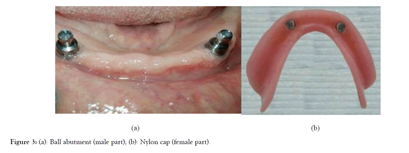
Group BS: Received Ball and Socket attachment (Implant Direct LLC, USA, Canada) in the form of
Male part: Consisting of metallic ball abutment of cuff height 2 mm (Figure 3a). Ball abutment was screwed onto the implant using hex tool. Complete seating of the abutments on their corresponding implants was verified by radiographing the implant abutment interface.
Figure 3. (a): Ball abutment (male part); (b): Nylon cap (female part).
Female part: Consisting of resilient nylon cap snapped in metal housing to be picked-up in the denture fitting surface (Figure 3b).
Pick-up procedures
The mandibular overdenture base was relieved to accommodate the newly inserted attachments. The denture was tried in the patient’s mouth to ensure complete seating. Any undercuts were blocked out using temporary filling (Litark, Lascod SpA-Vita L. Longo, Sesto F, no Firenze, Italy). A mix of self-cure acrylic resin (Lucitone 199; Dentsply) was applied in the relieved region for direct pick- up of the female part of OT Equator profile attachment, the male part of GPS attachment and the nylon caps of the Ball attachment using close-mouth technique.
Follow-up evaluation schedule
Evaluation was scheduled at the denture insertion, three, six and twelve months following denture insertion. At these intervals, patients return for assessment of implant, prostheses' function and standardized evaluation of his oral health. CBCT was used to identify peri-implant radiolucencies and bone level.
Radiographic evaluation using Cone Beam Computed Tomography (CBCT)
Images were acquired using the Scanora 3D Imaging system (Scanora 3D, Sorredex-Finland) (voxel size 133 μm-350 μm). The patients were exposed in the sitting position and the mandibles were immobilized by means of a head band to position the head against the head rest and chin cup, with the midsagittal plane perpendicular to the horizontal plane using vertical and horizontal alignment beams as recommended by the manufacture.
The procedure was repeated for each patient to monitor the changes in bone height for each implant.
Measurements for evaluation of crestal bone height
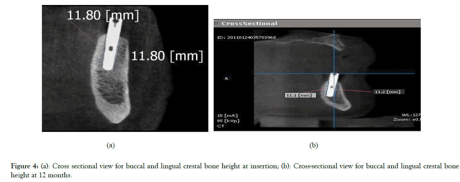
Crestal bone levels at buccal, lingual, mesial and distal were calculated from the reconstructed implant views by drawing a line parallel to the implant serration extending from the crestal bone to the apical end of the implant (Figure 4a and 4b). Average readings of the four surfaces at each interval were calculated and tabulated for statistical analysis.
Figure 4. (a): Cross sectional view for buccal and lingual crestal bone height at insertion; (b): Cross-sectional view for buccal and lingual crestal bone height at 12 months.
Statistical analysis
The data are expressed as the mean ± Standard Deviation (SD). The results were analyzed via two-way (ANOVA) to compare between groups at different time periods, followed by Tukey test for pairwise comparisons (intergroup comparison) and one-way analysis of variance (ANOVA) to compare between different groups at the same time. All tests were done by by GraphPad Prism version 7.00 (GraphPad Software, San Diego, CA). p-values<0.05 considered statistically significant.
Results
Table 1 shows comparison between mean differences of crestal bone height surrounding the implants in all studied groups at different intervals of follow-up period.
| Group OT: OT Equator profile attachment | Group GPS: GPS attachment | Group BS: Ball and Socket attachment | p-value | ||||
|---|---|---|---|---|---|---|---|
| Period | Mean difference (mm) | SD | Mean difference (mm) | SD | Mean difference (mm) | SD | - |
| 0-3 months | 0.252 | 0.01 | 0.234 | 0.011 | 0.306*# | 0.019 | <0.0001 |
| 3-6 months | 0.261 | 0.01 | 0.221* | 0.014 | 0.336*# | 0.021 | <0.001 |
| 6-12 months | 0.431 | 0.039 | 0.404* | 0.03 | 0.548*# | 0.017 | <0.05 |
*Statistically significant difference in comparison to Group OT at the same time interval at p<0.05
#Statistically significant difference in comparison to Group GPS at the same time interval at p<0.05
Table 1: Comparison between mean difference of crestal bone height surrounding the implants in all studied groups at different intervals of follow-up period.
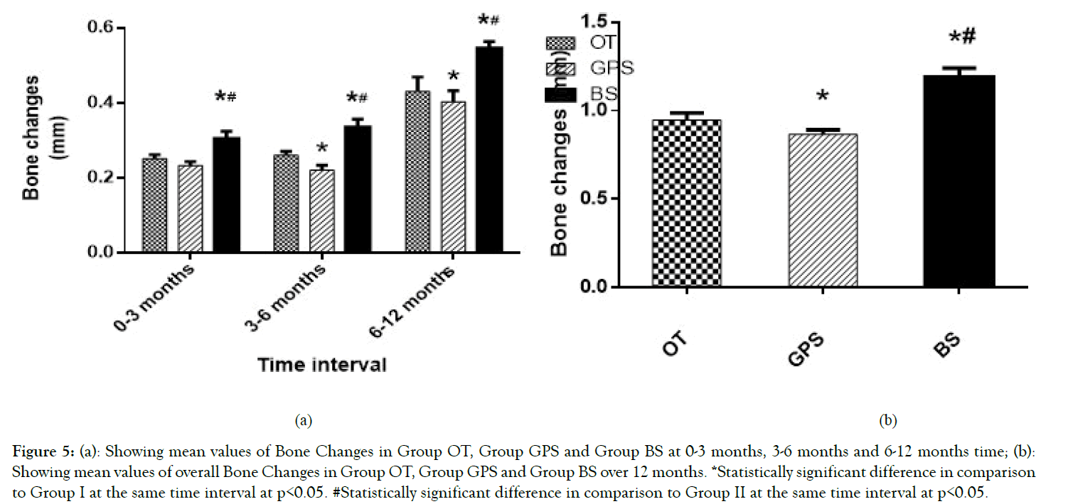
Figure 5a showing mean values of Bone Changes in Group OT, Group GPS and Group BS at 0-3 months, 3-6 months and 6-12 months’ time.
Figure 5. (a): Showing mean values of Bone Changes in Group OT, Group GPS and Group BS at 0-3 months, 3-6 months and 6-12 months time; (b): Showing mean values of overall Bone Changes in Group OT, Group GPS and Group BS over 12 months. *Statistically significant difference in comparison to Group I at the same time interval at p<0.05. #Statistically significant difference in comparison to Group II at the same time interval at p<0.05.
Figure 5b showing mean values of overall Bone Changes in Group OT, Group GPS and Group BS over 12 months.
Discussion
Only men were recruited for this study to avoid the effect of female hormonal changes on oral mucosa and bone [24,25].
CBCT was chosen in this study to determine the amount of marginal bone loss around implants based on its reported accuracy and precision. It is utilized successfully whenever direct measurements of bone height and density are required due to the fact that periapical and panoramic radiography ignore the bone density and height at the buccal and lingual surfaces [26].
The decreased amount of crestal bone resorption associated with Group GPS in comparison to Group OT and Group BS might be attributed to the difference in the abutment designs of the three groups. In case of GPS attachment the abutment connected to the implant is the female part which transfers the fulcrum point close to the fixture thus reducing lever arm and torque and allowing less crestal bone resorption [27].
Group BS also showed greater bone changes at the end of one year than Group OT, which could be due to the latter's low profile design, creating a favorable effect and causing less crestal bone loss [27].
These results are within the acceptable range of implant success which has shown a mean marginal bone loss around dental implants of 1.5 mm-2 mm in the first year after prosthetic restoration and 0.1 mm-0.2 mm annually after that [28,29].
This bone reduction might be due to surgical trauma, bone osteotomy and healing process. Also it might be considered an immediate bone reaction after insertion of the prosthesis and the functional stresses following prosthesis connection [26].
Conclusion
Within the limitations of this study it can be concluded that: GPS is least destructive to crestal bone around implants, however bone changes associated with Equator and Ball and socket implant attachments remained within the permissible range of crestal bone loss. Further studies are required to pursue the outcome of this study.
Conflict of Interest
No conflict of interest.
The Ethics Committee's Approval
The approval of Ethics committee is added in Annexure A.
REFERENCES
- Boerrigter EM, Stegenga B, Raghoebar GM, Boering G. Patient satisfaction and chewing ability with implant-retained mandibular overdentures: a comparison with new complete dentures with or without preprosthetic surgery. J Oral Maxillofac Surg. 1995;53:1167-1173.
- Meijer HJ, Raghoebar GM, Van't Hof MA, Geertman ME, Van Oort RP. Implant-retained mandibular overdentures compared with complete dentures; a 5-years' follow-up study of clinical aspects and patient satisfaction. Clin Oral Implants. 1999;10:238-244.
- Naert I, Gizani S, Vuylsteke M, Van Steenberghe D. A 5-year prospective randomized clinical trial on the influence of splinted and unsplinted oral implants retaining a mandibular overdenture: prosthetic aspects and patient satisfaction. J Oral Rehabil. 1999;26:195-202.
- Awad MA, Locker D, Korner-Bitensky N, Feine JS. Measuring the effect of intra-oral implant rehabilitation on health-related quality of life in a randomized controlled clinical trial. J Dent Res. 2000;79:1659-1663.
- Awad MA, Lund JP, Shapiro SH, Locker D, Klemetti E, Chehade A, et al. Oral health status and treatment satisfaction with mandibular implant overdentures and conventional dentures: a randomized clinical trial in a senior population. Int J Prosthodont. 2003;16:390-396.
- Heydecke G, Locker D, Awad MA, Lund JP, Feine JS. Oral and general health related quality of life with conventional and implant dentures. Community Dent Oral Epidemiol. 2003;31:161-168.
- Feine JS, Carlsson GE, Awad MA, Chehade A, Duncan WJ, Gizani S, et al. The McGill consensus statement on overdentures. Mandibular two-implant overdentures as first choice standard of care for edentulous patients. Gerodontol. 2002;19:3-4.
- Naert I, Quirynen M, Theuniers G, van Steenberghe D. Prosthetic aspects of osseointegrated fixtures supporting overdentures. A 4-year report. J Prosthet Dent. 1991;65:671-680.
- Phillips K, Wong KM. Space requirements for implant-retained bar-and-clip overdentures. Compend Contin Educ Dent. 2001;22:516-522.
- Preiskel HW. Stud attachments and magnets. In: Overdentures made easy: A guide to implant and root supported prostheses. London: Quintessence. 1996:89-97.
- Pasciuta M, Grossmann Y, Finger I. A Prosthetic solution to restoring the edenulous mandible with limited interarch space using an implant tissue supported overdenture: A clinical report. J Prosthet Dent. 2005;93:116-120.
- Cune M, Burgers M, van Kampen F, de Putter C, van der Bilt A. Mandibular overdentures retained by two implants: 10-year results from a crossover clinical trial comparing ball-socket and bar-clip attachments. Int J Prosthodont. 2010;23:310-317.
- Cune MS, de Putter C, Hoogstraten J. Treatment outcome with implant retained overdentures: part I-clinical findings and predictability of clinical treatment outcome. J Prosthet Dent. 1994;72:144-195.
- Cune M, van K, van der Bilt A, Bosman F. Patient satisfaction and preference with magnet, bar-clip and ball-socket retained mandibular overdentures: A cross-over clinical trial. Int J Prosthodont. 2005;18:99-105.
- Wittwer G, Adeyemo WL, Wagner A, Enislidis G. Computer-guided flapless placement and immediate loading of four conical screw-type implants in the edentulous mandible. Clin Oral Implants Res. 2007;18:534-539.
- Ganz S. Conventional CT and cone beam CT for improved dental diagnostics and implant planning. Dent Implantol Update. 2005;16:89-95.
- Rossi R, Morales RS, Frascaria M, Benzi R, Squadrito N. Planning implants in the esthetic zone using a new implant 3D navigation system. Eur J Esthet Dent. 2010;5:172-188.
- Loubele M, van Assche N, Carpentier K, Maes F, Jacobs R, van Steenberghe D, et al. Comparative localized linear accuracy of small-field cone-beam CT and multislice CT for alveolar bone measurements. Oral Surg Oral Med Oral Pathol Oral Radiol Endod. 2008;105:512-518.
- Ludlow JB. Regarding 'Influence of CBCT exposure conditions on radiation dose. Oral Surg Oral Med Oral Pathol Oral Radiol Endod. 2008;106: 627-628.
- Viegas VN, Dutra V, Pagnoncelli RM, de Oliveira MG. Transference of virtual planning and planning over biomedical prototypes for dental implant placement using guided surgery. Clin Oral Implants Res. 2010;21:290-295.
- Boerrigter EM, Geertman ME, van Oort RP, Bouma J, Raghoebar GM, van Waas MA, et al. Patient satisfaction with implant retained mandibular overdentures. A comparison with new complete dentures not retained by implants-a multicentre randomized clinical trial. Br J Oral Maxillofac Surg. 1995;33:282-288.
- Fontijn-Tekamp FA, Slagter AP, van Der Bilt A, van ‘T Hof MA, Witter DJ, Kalk W, et al. Biting and chewing in overdentures, full dentures, and natural dentitions. J Dent Res. 2000;79:1519-1524.
- Mish C. Classification of partially and completely edentulous arches in implant dentistry. In: Contemporary implant dentistry. St. Louis. C.V. Mosby, 1993:201-221.
- Tortopidis D, Lyons MF, Baxendale RH. The variability of bite force measurement between sessions indifferent positions within the dental arch. J Oral Rehabil. 1998;25:681-686.
- Shinogaya T, Bakke M, Thomson CE. Effects of ethnicity, gender and age on clenching force and load distribution. Clin Oral Investig. 2001;5:63-68.
- Hohlweg MC, Metzger BT, Kummerc D, Schulze B. Hohlweg- Majert B. Morphometric analysis- Cone beam computed tomography to predict bone quality and quantity. J Craniomaxillofac Surg. 2010;10:1016.
- Jingade RK, Rudraprasad IV, Sangur R. Biomechanics of dental implants: A FEM study. J Indian Prosthodont Soc. 2005;5:18-22.
- Ibrahim AM. Influence of platform switching on crestal bone changes at non-submerged straight and inclined implants retaining mandibular overdentures. Cairo Dental J. 2009;25:205-218.
- Goodacre CJ, Bernal G, Rungcharassaeng K, Kan JYK. Clinical complications with implants and implant prostheses. J Prosthet Dent. 2003;90:121-132.
Citation: Rizk FN, Shafei SFE (2020) Radiographic Bone Changes Surrounding Implants of Different Attachment Systems. Dentistry 10:557. doi: 10.35248/2161-1122.20.10.557
Copyright: © 2020 Rizk FN, et al. This is an open-access article distributed under the terms of the Creative Commons Attribution License, which permits unrestricted use, distribution, and reproduction in any medium, provided the original author and source are credited.
Sources of funding : Nil
