
Indexed In
- Genamics JournalSeek
- JournalTOCs
- CiteFactor
- RefSeek
- Hamdard University
- EBSCO A-Z
- OCLC- WorldCat
- Publons
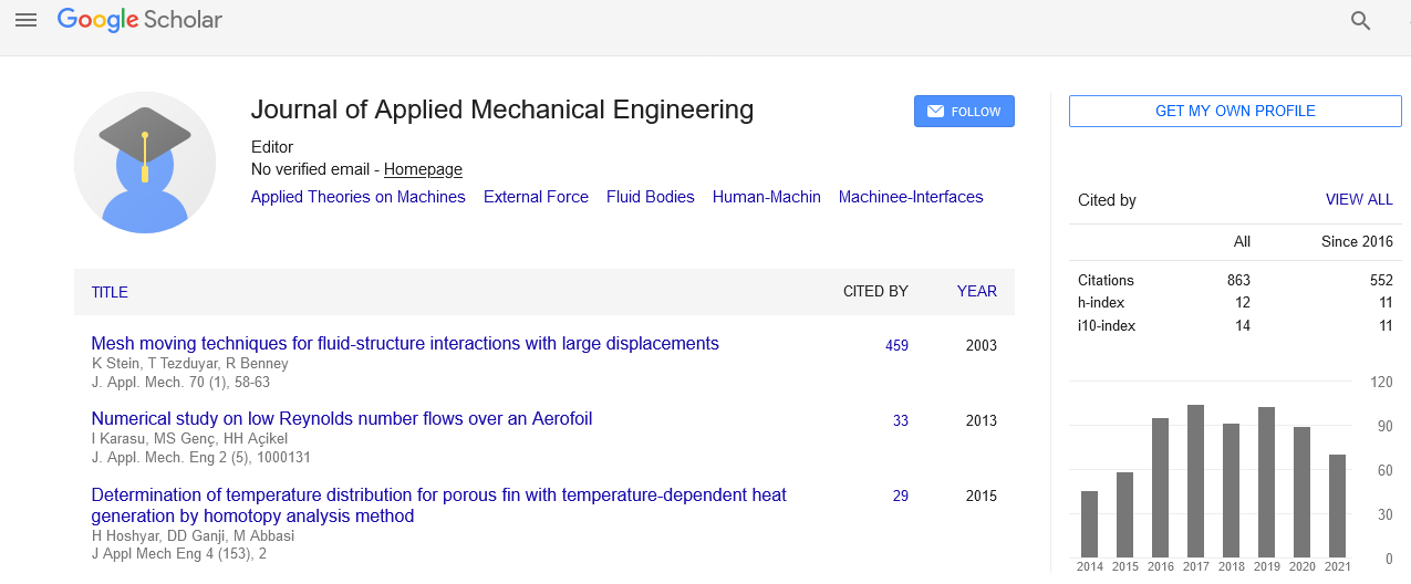
- Google Scholar
Useful Links
Share This Page
Journal Flyer
Open Access Journals
- Agri and Aquaculture
- Biochemistry
- Bioinformatics & Systems Biology
- Business & Management
- Chemistry
- Clinical Sciences
- Engineering
- Food & Nutrition
- General Science
- Genetics & Molecular Biology
- Immunology & Microbiology
- Medical Sciences
- Neuroscience & Psychology
- Nursing & Health Care
- Pharmaceutical Sciences
Opinion Article - (2023) Volume 12, Issue 1
Development of Intelligent Finite Element Method for Rapid Prototypes
Sandra Lory*Received: 02-Jan-2023, Manuscript No. JAME-23-20848; Editor assigned: 05-Jan-2023, Pre QC No. JAME-23-20848 (PQ); Reviewed: 19-Jan-2023, QC No. JAME-23-20848; Revised: 26-Jan-2023, Manuscript No. JAME-23-20848 (R); Published: 03-Feb-2023, DOI: 10.35248/2168-9873.23.12.462
Description
Designing of engineering and science applications involve many mathematical equations due to their complexity in terms of geometry of products and the usage of products. It cannot be the exactly defined equations for all sorts of applications and only empirical relationship would work in most of the situations. Methods such as discretization of shapes into small units of sizes, analyzing their behavior for stress, strain, heat conduction, electrical conduction can be understood to some extent by using different commercial softwares that use the concept of finite element methods using Finite Element Analysis (FEA). The socalled small element can be expressed in two dimensions or three dimensions. Each element can have different shape like triangle, square and so on. The behavior of the overall product can be understood by combining the results obtained for each element. In the process of analysis of the product, various factors are taken into consideration as the material of the product, the boundary conditions of the product, mechanical property evaluation, are used for evaluation.
Defining a material for a product plays an important factor to evaluate its deformation behavior. The amount of deformation of a product depends upon the elasticity–plasticity behavior of a material. Also, the temperature under which is product is subjected to work. The amount of load on the product is in regarding point load and uniformly distributed load. The type of intermediate fasteners used in the product is a different material property. When two products of different material are in action due to the presence of mechanical stress, each product experiences a different amount of stress–strain behavior. As the composition of the material in a product cannot be uniformly distributed, the plasticity behavior may not be exactly proportional, and the regaining behavior will not result in original shape. Boundary problems are solved using material models in finite element analysis. In a material model current stress-strain state is updated.
A stiffness matrix is assembled. Different methods have been adopted to formulate stiffness matrix. For designing rapid prototype, stiffness matrix calculation is a must. In the FEM, the structure of a product under analysis can be made into small elements of different shapes like shell element, frame element, plane element and plate elements. Different combination of elements can be used to model a product’s structure. The type of element used at the different location in a product depends upon the shape of the product at a location. Splitting up a product under FEM analysis is the fundamental requirements. The meaning of Finite Element (FE) refers to the split up of the model into finite sizes.
Conclusion
These finite sizes represent elements the choice of the elements is based on the expertise of the finite element analyst. Each element has minimum two end points. An element can be represented by a matrix. The matrix contains values of nodes. The adjacent elements can be represented by many matrices. These matrices are assembled according to the connectivity of the elements. By solving the matrix, stress and strain can be obtained at nodes of all the finite elements. The form of the design is broken into non-overlapping coupled components called elements. These elements are represented by a linear combination of polynomial functions with undetermined coefficients, which form the approximate numerical solution to the governing differential equations. The undetermined coefficients are represented by nodes, which are located on the ends of an element. The solutions are found at these nodes using the polynomial functions and prescribed boundary conditions.
Citation: Lory S (2023) Development of Intelligent Finite Element Method for Rapid Prototypes. J Appl Mech Eng. 12:462.
Copyright: © 2023 Lory S. This is an open-access article distributed under the terms of the Creative Commons Attribution License, which permits unrestricted use, distribution, and reproduction in any medium, provided the original author and source are credited.