Indexed In
- Genamics JournalSeek
- JournalTOCs
- CiteFactor
- RefSeek
- Hamdard University
- EBSCO A-Z
- OCLC- WorldCat
- Publons
- Google Scholar
Useful Links
Share This Page
Journal Flyer
Open Access Journals
- Agri and Aquaculture
- Biochemistry
- Bioinformatics & Systems Biology
- Business & Management
- Chemistry
- Clinical Sciences
- Engineering
- Food & Nutrition
- General Science
- Genetics & Molecular Biology
- Immunology & Microbiology
- Medical Sciences
- Neuroscience & Psychology
- Nursing & Health Care
- Pharmaceutical Sciences
Research Article - (2023) Volume 12, Issue 5
Design Life Estimation of Commercial Aircraft Wing through Structural and Aerodynamic Analysis at various Altitudes and Angles of Attack
Dildar Ahmed1 and Ali Javed2*2Department of Mechanical Engineering, Institute of Space Technology, Islamabad, Pakistan
Received: 28-Jun-2023, Manuscript No. JAME-23-21970; Editor assigned: 30-Jun-2023, Pre QC No. JAME-23-21970 (PQ); Reviewed: 14-Jul-2023, QC No. JAME-23-21970; Revised: 21-Jul-2023, Manuscript No. JAME-23-21970 (R); Published: 28-Jul-2023, DOI: 10.35248/2168-9873.23.12.500
Abstract
Design life estimation has been a reason of concern in design of commercial aircraft wings since it incorporates the study of various parameters that are interconnected. This study focusses on the aerodynamic and structural analysis of Airbus A320 wing at various Mach numbers and angles of attack. Aerodynamic pressure loads are calculated by performing CFD (Computational Fluid Dynamics) on the skin surface of wing. CFD loads are then transfer to the internal structural components of wing (ribs, spars) for structural analysis. The study gives estimates of stresses and deformations on internal structural members against aerodynamic loads and identified stress concentration areas which will subsequently be used for determining the remaining life of aircraft wing and structural behavior at different angles of attack.
Keywords
Aircraft wing; Aerodynamic loads; Structural analysis; Structural behavior; Design life; CFD; FEM; FEA; Altitudes; Angles of attack.
Introduction
Aerodynamic and structural analysis of a wing at different angles of attack is an important part of the design process for aircraft wings. The angle of attack is the angle between the wing chord line and the direction of the airflow, and it has a significant impact on both the aerodynamic and structural performance of the wing. At low angles of attack, the wing generates lift primarily through the Bernoulli Effect, which results in a pressure differential between the upper and lower surfaces of the wing. As the angle of attack increases, however, the airflow over the wing becomes increasingly turbulent, which can lead to stall and loss of lift. Aerodynamic analysis of the wing at different angles of attack involves using CFD simulations and mathematical models to study the airflow over and around the wing. This allows engineers to visualize the flow patterns and identify areas of high turbulence or drag. The results of this analysis can be used to optimize the wing shape and size to achieve desired performance characteristics such as lift, drag, and stability at different angles of attack. Structural analysis of the wing at different angles of attack involves using FEA (Finite Element Analysis) simulations and mathematical models to study the stresses and deformations that occur in the wing structure. This allows engineers to design a wing that is strong enough to withstand the loads it experiences during flight at different angles of attack. The results of this analysis can be used to optimize the material used for the wing, alter the thickness or shape of different sections of the wing, or add additional support structures to reinforce weak areas. Overall, aerodynamic and structural analysis of the wing at different angles of attack is critical in the design process for aircraft wings. By optimizing the design of the wing to achieve desired performance characteristics at different angles of attack, engineers can help to maximize the performance and efficiency of the aircraft.
Literature Review
Computation analysis of aerodynamic components such as aircraft wing poses significant challenges to designers and engineers due to the involvement of various structural and aerodynamic complexities. Design and analysis of aircraft wings have been studied by many engineers and publications related to this topic are also numerous. However few publications can be segregated as benchmark to help conduct this analysis.
Zakuan in his paper have highlighted the important parameters for Computer-Aided Design (CAD) modeling of full scale aircraft wing [1]. Same parameters have also been in this study for model generation. The paper conducts the three-dimensional analysis of A320 wing for two different cases and further highlights that the configuration of spars play huge role in determining the load bearing capacity of the wing. Static structural and model analysis has been conducted and validation of results has been performed from past study using ANSYS. Jadhav has performed structural analysis on BOEING BACXXX airfoil on two different configurations; first using aluminium alloy and second using titanium alloy [2]. It has been concluded that the latter case shows less deformation as compared to the former one. Kumar in his study carries the static and fatigue analysis of trainer aircraft wing with winglets at two different angles (45° and 25°) [3]. The study uses NACA64215 aerofoil configuration and range of materials like (s2-glass, Kevlar-49 and boron fiber). Results suggest that boron fiber present better material due to its least stress bearing at winglet of the aircraft. Raj in his study uses composite wing to predict the failure in aircraft wing [4]. It is concluded that composite is capable of withstanding the loads without undergoing failure. Hassan uses slotted wing configuration to enhance lift on various flight scenarios [5]. The study shows that lift coefficient is highest (0.489) at -3% depth of the chord and decreases when depth of the slat becomes 0%. It rises when depth reaches to 4% and never touches the maximum with highest drag coefficient (1.89) at 4% of the wing chord. Wunderlich in his detailed study gives assessment of more flexible wing concept. The paper shows trade-off between aerodynamic properties and wing mass [6]. The paper shows trade-off between aerodynamic properties and wing mass. Tang in his paper proposes a finite element parametric modeling method for aircraft wing structures to address the time- consuming nature of finite element analysis pre-processing [7]. The focus is on the preliminary design phase of aircraft structures. A knowledge-driven system of fast finite element modeling is developed, encapsulating design methods, rules, and expert experience to automatically establish a finite element model using a template parametric technique. Ravindra in his article designed and analyzed a trapezoidal wing structure using three different materials: Aluminium, Carbon epoxy, and steel [8]. After thorough investigation, it was determined that Aluminium 7075-T6 emerged as the most suitable material for the aircraft wing. In comparison to Carbon epoxy and steel, Aluminium exhibited significantly lower deformation when subjected to self-weight. Shabeer in his study develops an accurate model for the optimal design of an aircraft wing by combining composite materials (skins) and isotropic materials (other structures) [9]. Static analysis is conducted using MSc Nastran, applying an inertia force of 1 g, and aerodynamic results (lift) are used to simulate the wing loading. The final design is determined by tabulating stress and displacement values for each ply combination. Sarojini proposed improved approach on the existing literature methods it is computationally efficient, provides reasonable accuracy for early-stage structural sizing and weight prediction, and includes dynamic effects [10]. Study conducted by Raj focuses on the structural analysis of an aeroplane wing utilizing the NACA (National Advisory Committee for Aeronautics) profile, conducted with three distinct materials through solidworks and ANSYS workbench software [11]. The proposed method aims to streamline the wing modeling and analysis process, effectively reducing experimentation costs and associated development time. Furthermore, the wing's configuration will be optimized to reduce weight and enhance stiffness by adopting appropriate sections for different components of the aeroplanes wing. This approach facilitates efficient product development, offering valuable insights for improving wing performance without compromising on safety and functionality. Rabbey emphasizes on elastic structures that regain their original shape and stress dissipates when external forces are removed [12]. Advanced aluminum is suggested for this purpose. While composite materials are the preferred choice for their mechanical strength, light weight, and resistance to thermal and corrosive effects, advanced aluminum is widely used in modern wing construction. The paper highlights the use of advanced aluminum in various aerospace components, such as wing skin panels, fuselage structures, and truss elements in spacecraft, antennas, and parabolic reflectors. Abbas in his study involves conducting a structural analysis of a typical transport aircraft wing [13]. The wing model, created using CATIA® V5 (Computer Aided Three-Dimensional Interactive Application), includes various structural components like spars, ribs, and skin. The model is then imported into the ANSYS® 2016 software for structural analysis. The study evaluates stresses, strains, deformations, and safety factors of the wing model. The analysis focuses on stresses induced by aerodynamic loads acting on the wing. Park shows multidisciplinary design optimization integrating structural and aerodynamic analysis using nonlinear behaviour and results demonstrated successful framework for MDO (Multidisciplinary Design Optimization) [14]. Oktay shows how topology can be used to determine optimum rib topology using two different spar positions [15]. Kilimtzidis conducted study on showing framework with high accuracy and efficiency for early design of composite aircraft wing [16].
Methodology
Development of CAD model
A 3D CAD model of wing was created using solidworks modeling software. The model further classified into to external and internal parts. External part consists of wing skin which is used for aerodynamic CFD analysis for pressure load calculations while internal part comprises ribs and spars which take these pressure loads resulting in generating stress concentration areas and deformations that can further used for life and damage calculations of structural members of wing. The 3D CAD Model was shown in Figure 1.

Figure 1: 3D CAD model of aircraft wing.
Aerodynamic analysis
An external part was used for aerodynamic analysis that was wing skin. For this purpose, Pressure far field computational domain was created and discretized it into number of control volumes as shown in Figure 2. ANSYS (Analysis System) fluent 19.2 was used for this purpose. Density based SST k-ω (Shear Stress Transport) turbulence model and explicit Roe Flux-Difference Splitting (ROE-FDS) green gauss cell based discretization scheme was used for aerodynamic analysis at different angle of attacks and Mach numbers. Environmental and boundary conditions for CFD analysis is shown in Table 1. The outcomes of CFD analysis is lift coefficient, drag coefficient and pressure loads corresponding to each case shown in Figure 3.
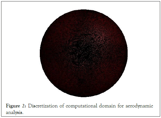
Figure 2: Discretization of computational domain for aerodynamic analysis.
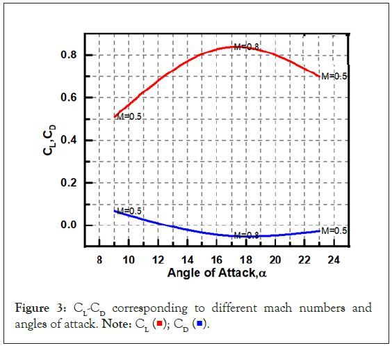
Figure 3: CL-CD corresponding to different mach numbers and angles of attack. Note: 
| Case | Altitude | Pressure (Pa) | Temperature (K) | AoA֯ | Mach No. |
|---|---|---|---|---|---|
| 1 | 5000 | 54020 | 255.65 | 23 | 0.5 |
| 2 | 1000 | 26436 | 223.15 | 17 | 0.8 |
| 3 | Sea level | 101325 | 288 | 9 | 0.5 |
Table 1: Operating and boundary conditions for different cases.
Structural analysis
The structural analysis was performed by using static structural module of ANSYS workbench 19.2. ANSYS Space Claim was used for the purpose of geometry cleaning. Gaps, missing faces, split edges, extra edges and interferences of various components were fixed in it. Meshing of the CAD models of wing was performed within the static structural module. Various meshing controls such as body sizing, face sizing, tetrahedron method and Hex dominant method were used to improve the quality of mesh. Element size was selected according to the minimum size of body within the CAD model. The quality of mesh was checked by applying the element quality. All the structural connections were built by using “Bonded” contact type. Bonded contact type restricted all the degree of freedom and don’t allow sliding between the mating surfaces. Contact tool was used to get the initial information of connections. Geometric gaps and geometric penetrations of the contacted surfaces were identified. The Pinball regions were assigned to contacts having geometric gaps with radius equal to the gap between bonded surfaces. The regions with geometric penetration were fixed in ANSYS space claim. Meshing of wing skin, ribs and spars are shown in Figure 4. Materials presented in Table 2 were assigned to the different components of wing.
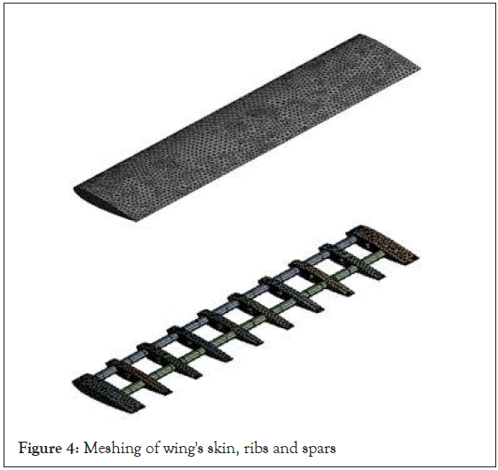
Figure 4: Meshing of wing's skin, ribs and spars
| Components | Material designation | Density (kg/m3) | Young’s modulus (GPa) | Poisson’s ratio |
|---|---|---|---|---|
| Skin | 7049-T73 | 2766 | 69 | 0.33 |
| Ribs | 7049-T73 | 2766 | 69 | 0.33 |
| Spar | Ti-6A-4V | 4508 | 117 | 0.33 |
Table 2: Materials assigned to wing components.
Fixed support was applied on root side of wing. It provides rigid support and constraints all degree of freedoms. CFD pressure was directly imported on the surface of wing for all three cases shown in Figures 5-7 respectively. The desired outputs of FEA analysis are the equivalent Von-Mises stresses and deformations shown in Figures 8-10 respectively.
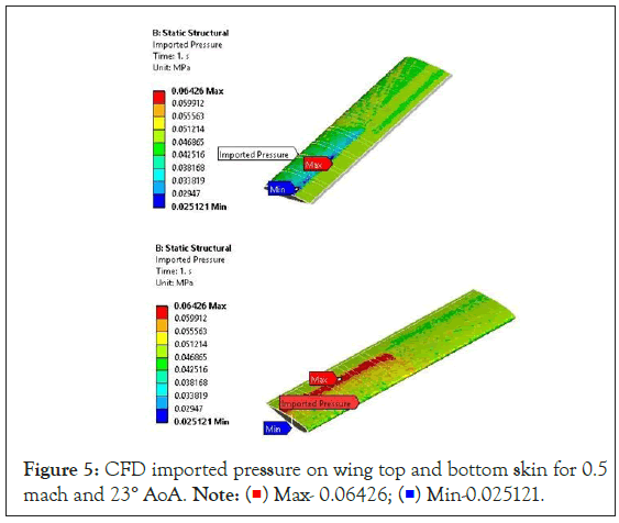
Figure 5: CFD imported pressure on wing top and bottom skin for 0.5 mach and 23° AoA. Note:  Max- 0.06426;
  Min-0.025121.
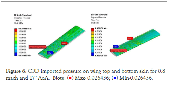
Figure 6: CFD imported pressure on wing top and bottom skin for 0.8 mach and 17° AoA. Note:  Max- 0.026436;
  Min-0.026436.
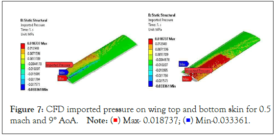
Figure 7: CFD imported pressure on wing top and bottom skin for 0.5 mach and 9° AoA. Note:  Max- 0.018737;
  Min-0.033361.

Figure 8: Equivalent (von-mises) stress distribution and total deformation on wing at 23° AoA. Note: Equivalent stress:  Max-307.66;
  Min-0.034798, Total deformation:
  Max- 64.933;
  Min-0.

Figure 9: Equivalent (von-mises) stress distribution and total deformation on wing at 17° AoA. Note: Equivalent stress:  Max-42.497;
  Min-0.010682, Total deformation:
  Max- 9.1421;
  Min-0.

Figure 10: Equivalent (von-mises) stress distribution and total deformation on wing at 9° AoA. Note: Equivalent stress:  Max-236.64;
  Min-0.02664, Total deformation:
  Max- 49.199;
  Min-0.
After FEA (Finite Element Analysis) of wing, damage and life calculations were done by using ANSYS Design Life n code 19.2. It is used for damage and life estimation of wing structures, as it is capable of analyzing the fatigue behavior of complex geometries and material properties under different loading conditions. The results are shown in Figures 11-13 respectively. The overall procedure for combine aerodynamic and finite element analysis to predict structural behavior of aircraft’s wing is shown in Figure 14.
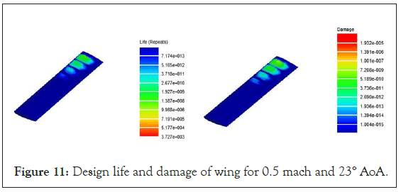
Figure 11: Design life and damage of wing for 0.5 mach and 23° AoA.

Figure 12: Design life and damage of wing for 0.8 mach and 17°AoA.
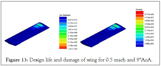
Figure 13: Design life and damage of wing for 0.5 mach and 9°AoA.
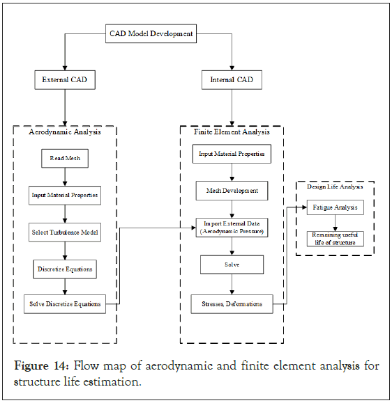
Figure 14: Flow map of aerodynamic and finite element analysis for structure life estimation.
Results and Discussion
The outcomes of FEA analysis for all three cases and their corresponding life cycles are shown in Table 3. Equivalent Von– Mises stress for CFD case (0.5 Mach and 23° AoA) with maximum value 130 MPa is higher than rest of the two cases, so it is the critical case and life cycles corresponding to this stress is calculated 1.927 × 10⁹. CFD (Computational Fluid Dynamics) and FEA (Finite Element Analysis) are two important analysis methods used in the design of aircraft wings. CFD is used to analyze the flow of air over the wing by using mathematical models and computer simulations, while FEA on the other hand involves breaking the wing down into small, interconnected elements and then calculating the stresses and strains in each element based on the aerodynamic forces acting on it. Overall, CFD and FEA are critical tools in the design of aircraft wings, allowing engineers to visualize the flow patterns and identify areas of high turbulence or drag and to design a wing that is strong enough to withstand the loads it experiences during flight, while also being as lightweight as possible to minimize fuel consumption.
| Case | Imported pressure (MPa) | Equivalent (Von-Mises) Stress (MPa) | Total deformation (mm) | Life (Cycles) |
|---|---|---|---|---|
| 0.5 Mach and 23° AoA | 0.0642 | 130 | 64.93 | 1.927 × 10⁹ |
| 0.8 Mach and 17° AoA | 0.0264 | 41.137 | 9.0326 | 1.845 × 10¹⁴ |
| 0.5 Mach and 9° AoA | 0.0187 | 97.6 | 49.199 | 4.601 × 10¹⁰ |
Table 3: Summary of result.
Conclusion
In Conclusion, aerodynamic and finite element analysis of commercial aircraft wing at three different angles of attack was done by using skin as external part and ribs and spars as an internal part. Materials assigned to structural members (skin, ribs and spars) of wing are aluminum alloy and titanium alloy. The desired outcome of aerodynamic analysis is pressure which is imported as an external data for finite element analysis in order to calculate stresses and deformations against these CFD loads on internal structure of wing. These stresses are used in fatigue analysis for design life calculation and structure optimization. For case 0.5 Mach and 23° AoA, the equivalent Von–Mises stress was found 130 MPa higher than rest of two (0.8 Mach and 17° AoA, 0.5 Mach and 9°AoA) case. So it is the critical case. Design life for critical case was 1.927 × 10⁹ cycles. To find more suitable material with good aerodynamic and structural characteristics, several materials can be tested for future correspondence.
Data Availability
The data used to support the findings of this study are available from the corresponding author upon request.
Funding
The author(s) received no specific funding for this study.
Conflicts of Interest
The authors declare that they have no conflicts of interest to report regarding the present study.
References
- Zakuan MAMBM, Aabid A, Khan S. Modelling and structural analysis of three-dimensional wing. Int J Eng Technol. 2019;9:6820–6828.
- Jadhav B. Modeling and structural analysis of aircraft wing using aluminium alloy and titanium alloy. Int J Eng Res Technol. 2020.
- Kumar PV, Raj IR, Reddy MS, Prasad NS. Design and finite element analysis of aircraft wing using ribs and spars. Turk J Math. 2021;12(8):3224–3230.
- Raj NN, Koti H. Static stress analysis for aircraft wing and its weight reduction using composite material. Int J Eng Res. 2014;3(3).
- Hassan MA, Laftah RM, Ismael MA. Numerical analysis of slotted wings using fluid-structure interaction. 2022.
- Wunderlich TF, Dähne S, Reimer L, Schuster A. Global aerostructural design optimization of more flexible wings for commercial aircraft. J Aircr. 2021;58(849):1254–1271.
- J. Tang, P. Xi, B. Zhang, B. Hu. A finite element parametric modeling technique of aircraft wing structures. Chinese J Aeronaut. 2013;26:1202–1210.
- Ravindra K, Raju PD. Analysis of aircraft wing with different materials using ansys software. Int Res J Eng Tech. 2017;4(10):1280–1285.
- Shabeer KP, Murtaza MA. Optimization of aircraft wing with composite material. Int J Innov Res Technol Sci Eng. 2013;2.
- Sarojini D. Structural analysis and optimization of aircraft wings through dimensional reduction. 2021.
- Raj SS. Numerical analysis of an aircraft wing. TURCOMAT. 2021;12(11):3760–3766.
- Rabbey MF, Rumi AM, Nuri FH, Monerujjaman HM, Hassan MM. Structural deformation and stress analysis of aircraft wing by finite element method. Adv Mat Res. 2014.
- Abbas Y, Elsonni T, Abdulmajid AA, Khalafallh A, Alnazir M. Structural analysis of a transport aircraft wing. INCAS Bull. 2021;13(1):3-9.
- Park C, Joh CY, Kim YS. Multidisciplinary design optimization of a structurally nonlinear aircraft wing via parametric modelling. Int J Precis Eng. 2009;10(2):87–96.
- Oktay E, Akay HU, Merttopcuoglu O. Parallelized structural topology optimization and CFD coupling for design of aircraft wing structures. Comput Fluids. 2011;49(1):141–145.
- Kilimtzidis S, Kotzakolios A, Kostopoulos V. Efficient structural optimisation of composite materials aircraft wings. Compos Struct. 2023;303:116268.
Citation: Ahmed D, Javed A (2023) Design Life Estimation of Commercial Aircraft Wing through Structural and Aerodynamic Analysis at various Altitudes and Angles of Attack. J Appl Mech Eng. 12:500.
Copyright: © 2023 Ahmed D, et al. This is an open-access article distributed under the terms of the Creative Commons Attribution License, which permits unrestricted use, distribution, and reproduction in any medium, provided the original author and source are credited.
